1990 CRX Electrical
Troubleshooting Manual
Welcome to the on-line electrical reference manual for the 1990 (90 & 91 in most cases, 88-89 will have slight differences and should not use this manual) Honda CRX.
If you would like to purchase a Honda service manual you can do so on-line at: http://www.helminc.com for a cost of $35 plus shipping or from Honda - part number 61SH202-EL. Important and commonly used sections are bolded.
1-1 Front Page
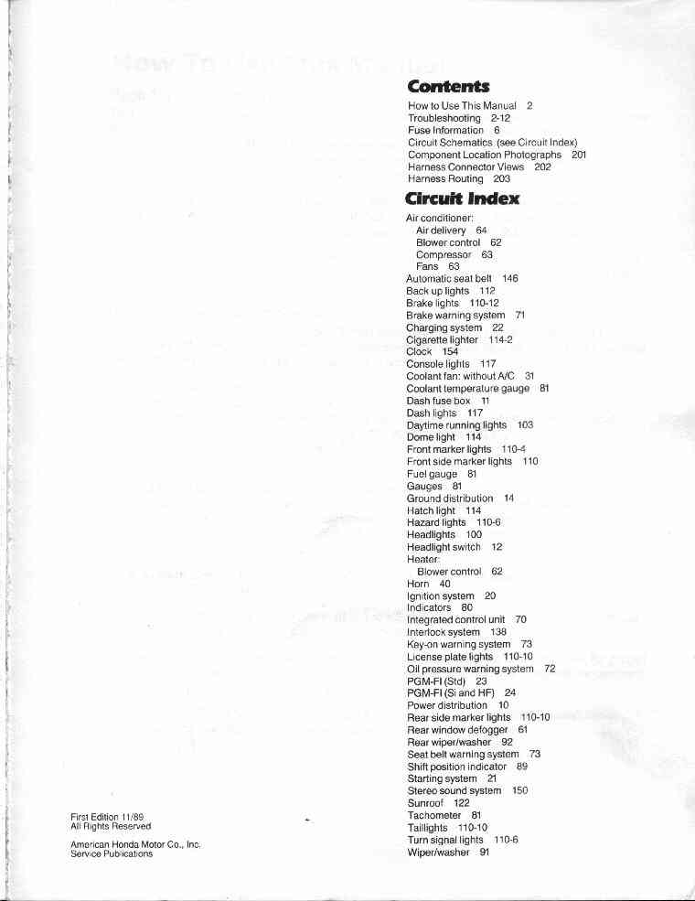
1-2 Circuit Index
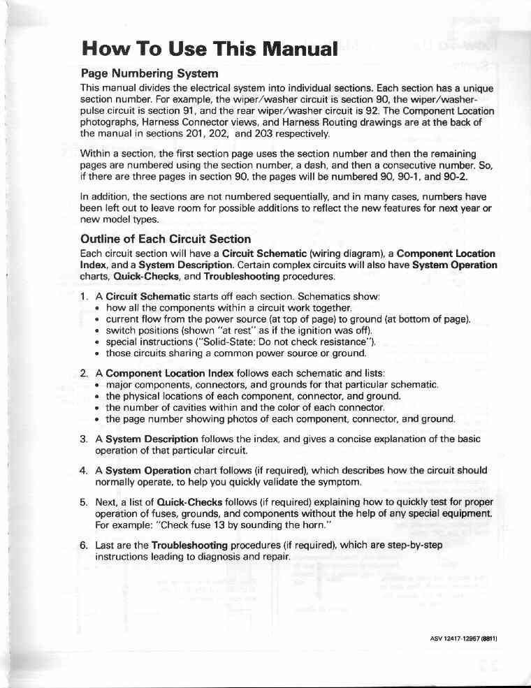
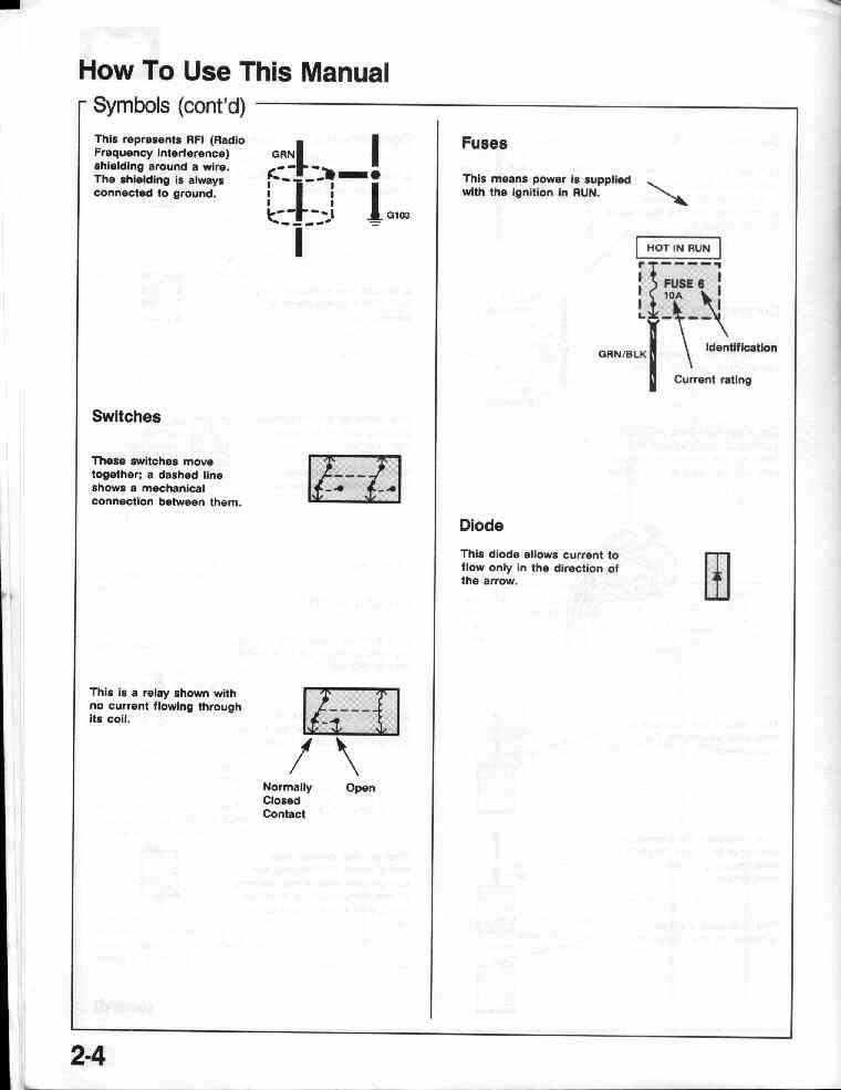
2-1 How To Use This Manual
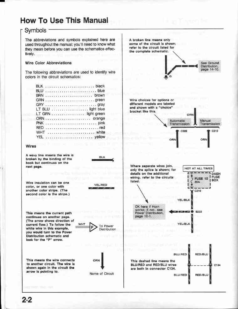
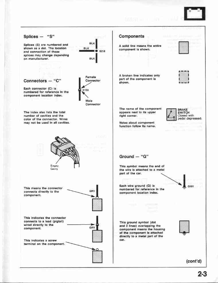
2-2 How To Use This Manual (Explanation of
Symbols used in the manual)
2-3,
2-4
2-6 How To Use This Manual (Explanation of
Circuit Diagrams and how to read)
2-7,
2-8, 2-9, 2-10
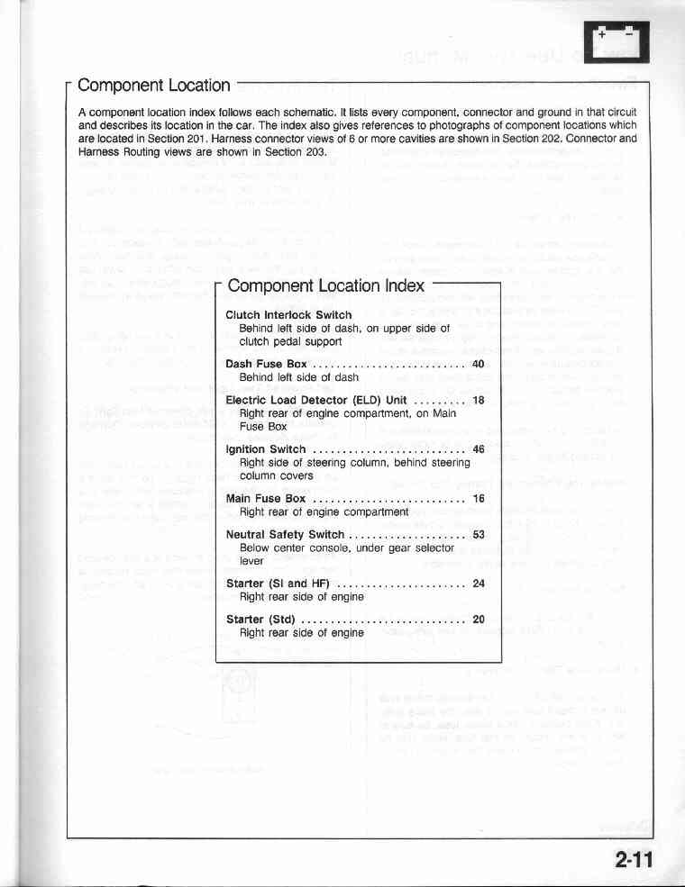
2-11 Component Location (Explanation)
2-12 How To Use This Manual (Five-Step
Troubleshooting)
2-12 How To Use This Manual (Using test
equipment)
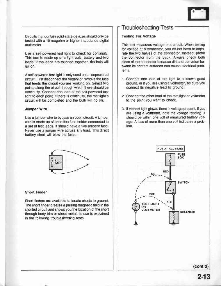
2-13
2-13 How To Use This Manual (Testing for
voltage)
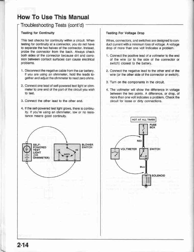
2-14 How To Use This Manual (Testing for continuity)
2-14 How To Use This Manual (Testing for
voltage drop)
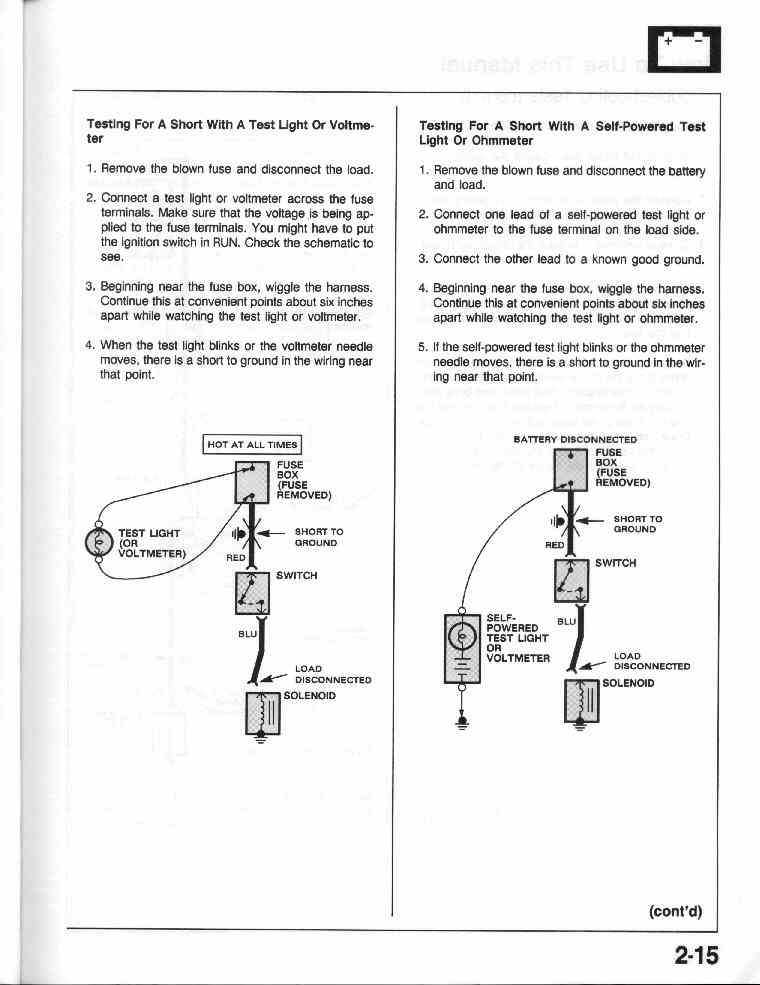
2-15 How To Use This Manual (Testing for a
short with a test light or voltmeter)
2-15 How To Use This Manual (Testing for a short
with a self-powered test light or ohmmeter)
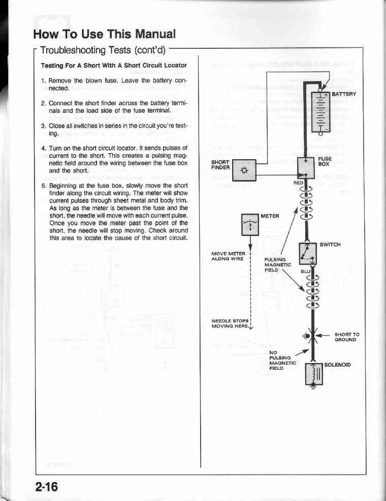
2-16 How To Use This Manual (Testing for a
short with a short circuit tester)
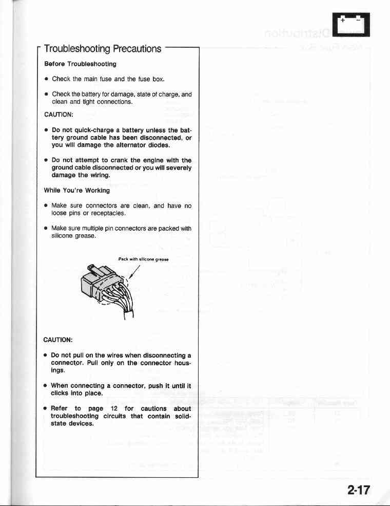
2-17 Troubleshooting Precautions
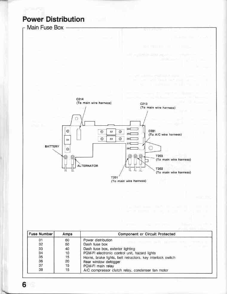
6-0 Main
Fuse Box - Under Hood (with fuse numbers and amp amounts)
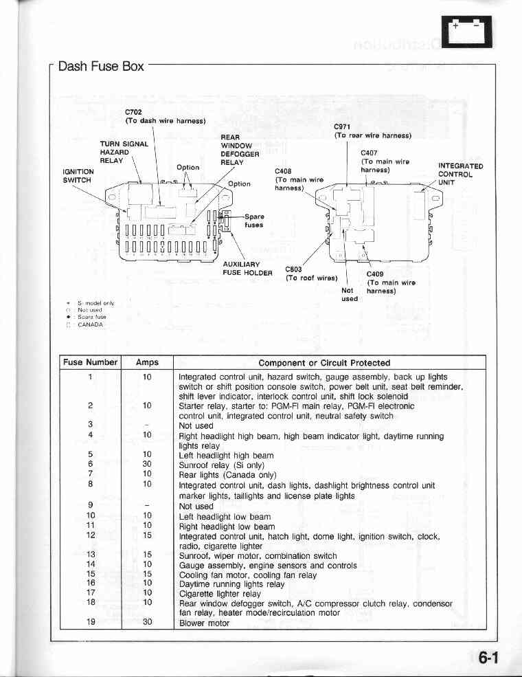
6-1 Dash Fuse Box (with fuse numbers and amp amounts)
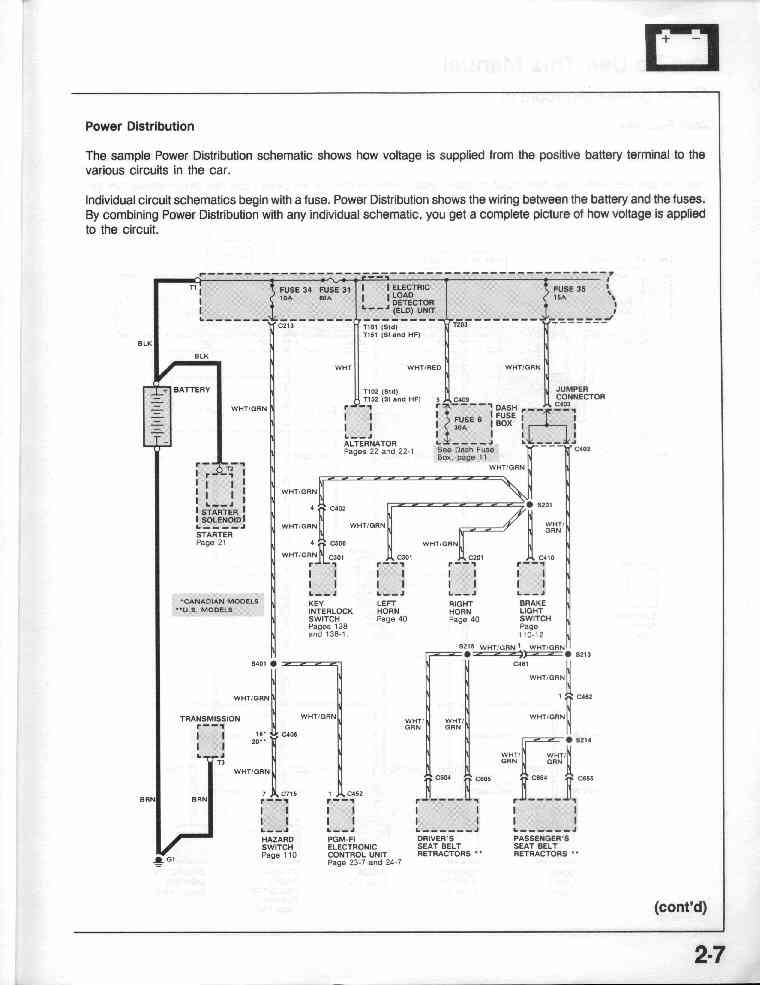
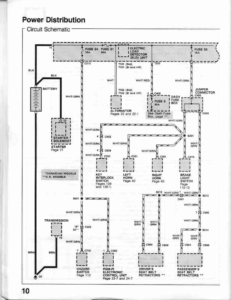
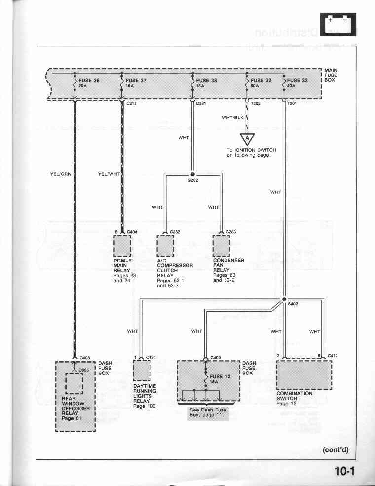
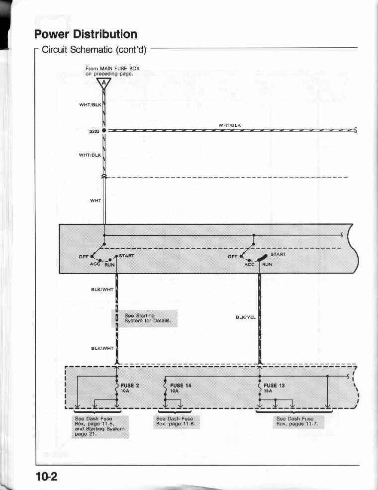
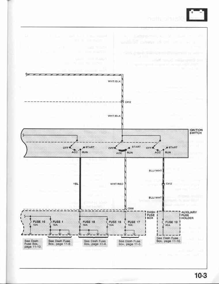
10-0 Major power lines with colors (Circuit Schematic)
10-1, 10-2, 10-3
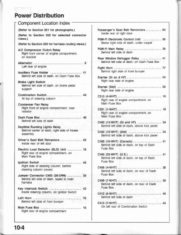
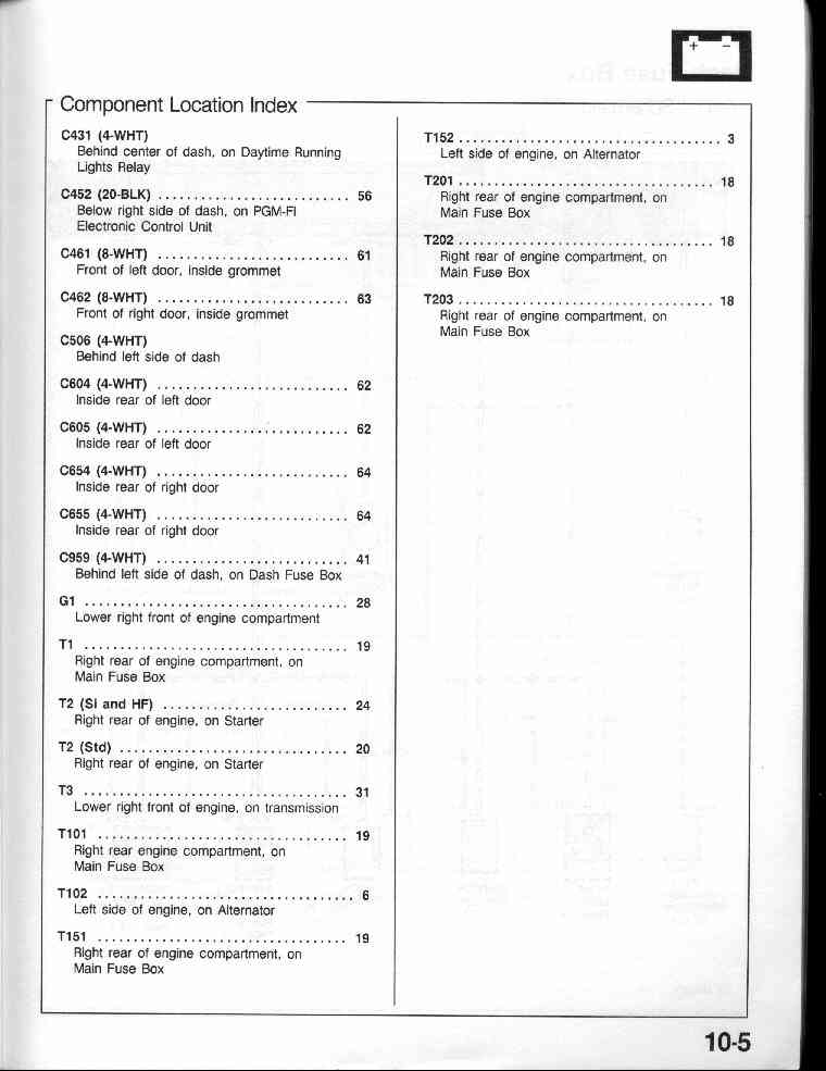
10-4 Power Distribution Component Location Index
10-5
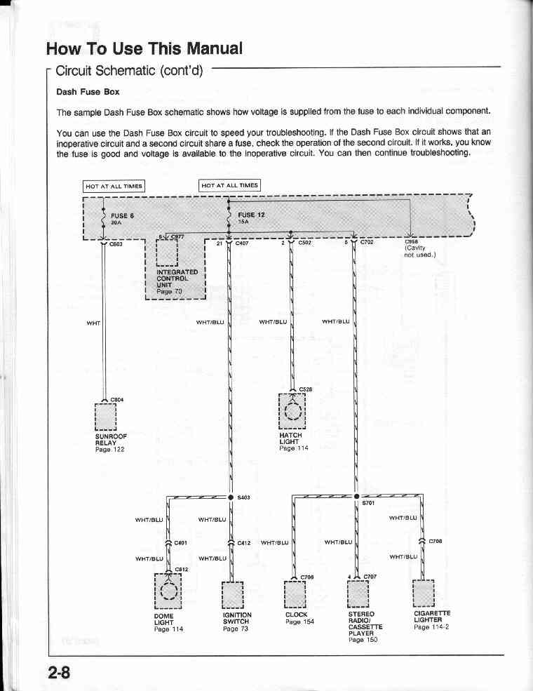
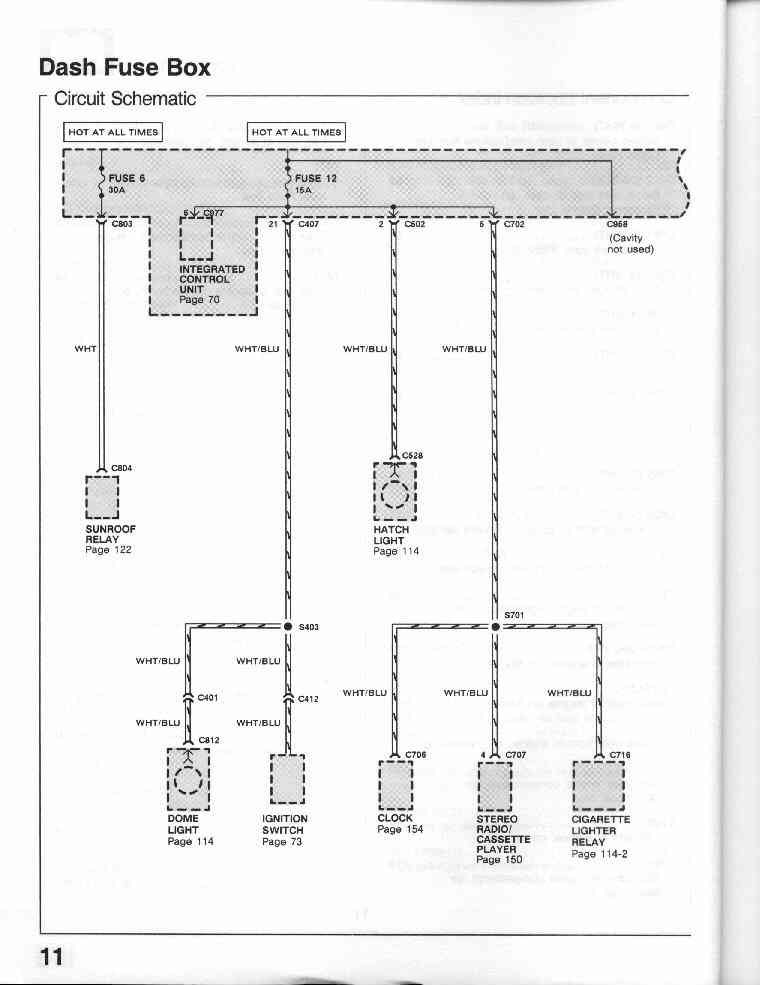
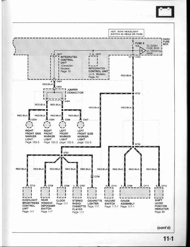
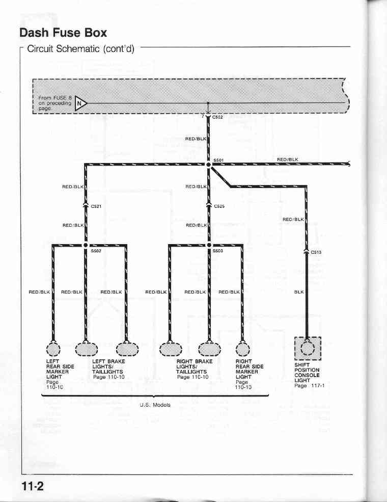
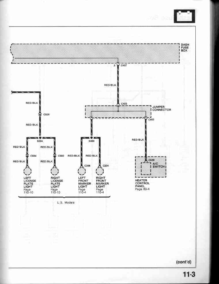
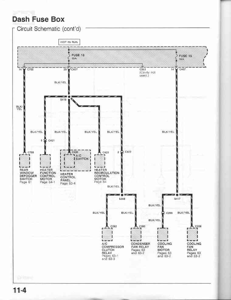
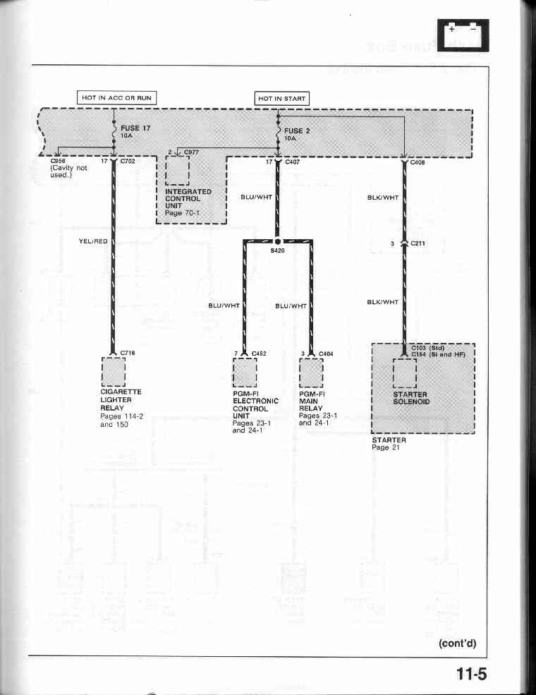
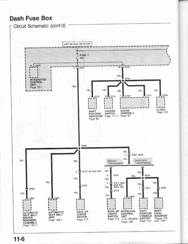
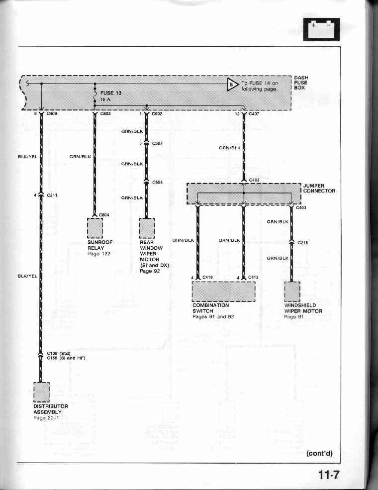
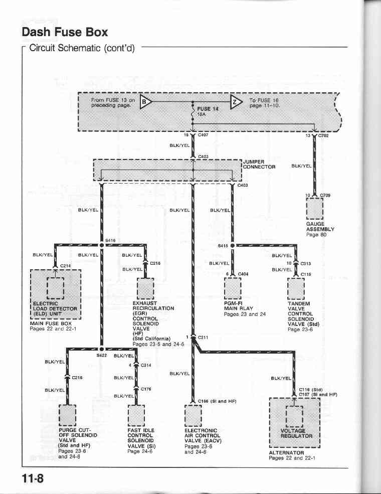
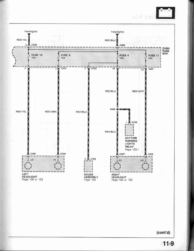
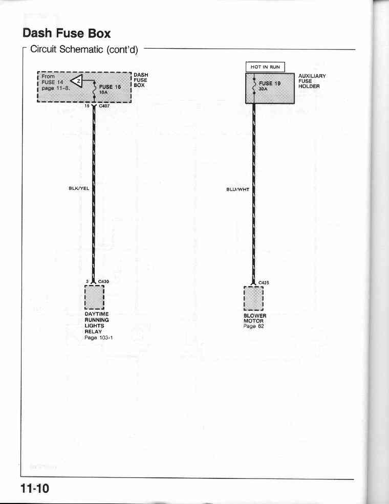
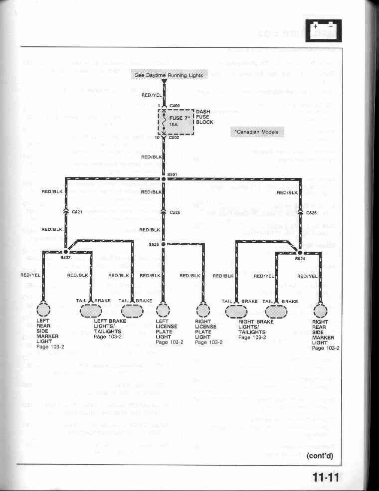
11-0 Dash Fuse Box (Circuit Schematic)
11-1, 11-2, 11-3,
11-4, 11-5, 11-6,
11-7, 11-8, 11-9,
11-10, 11-11
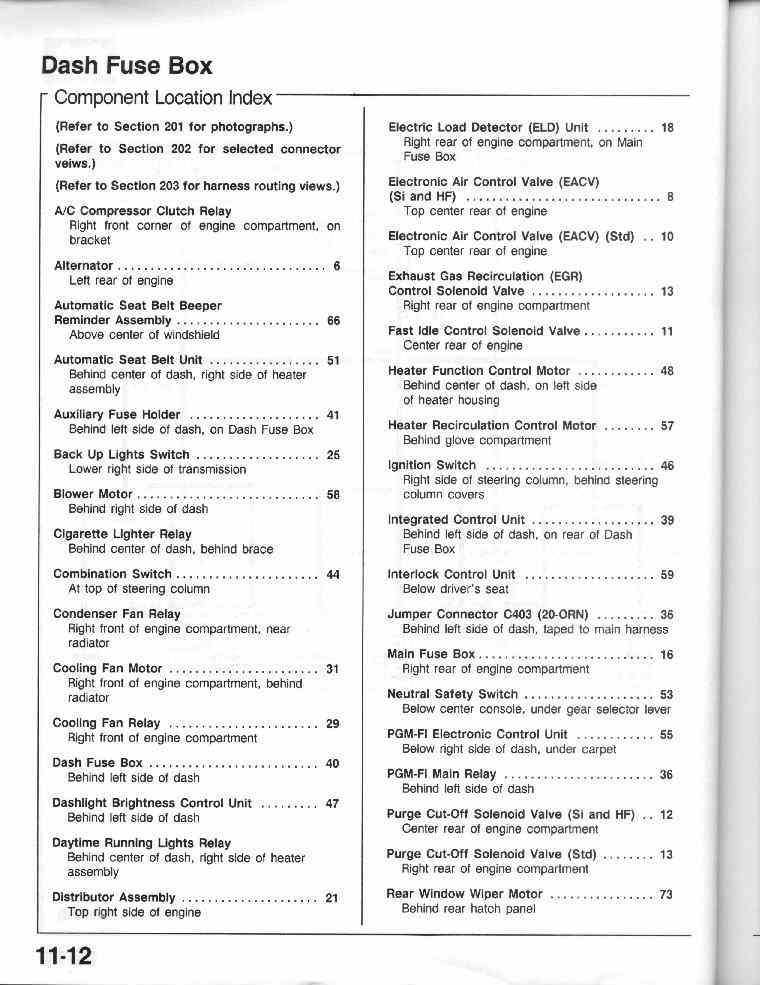
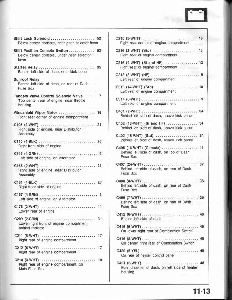
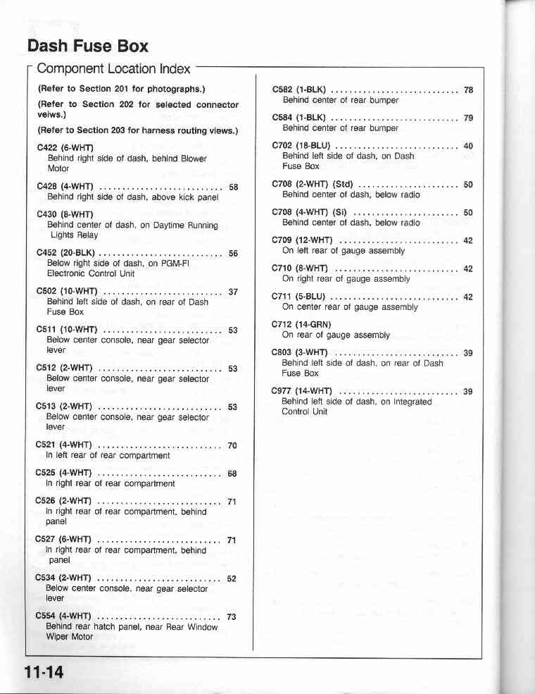
11-12 Dash Fuse Box (Component Location Index)
11-13, 11-14
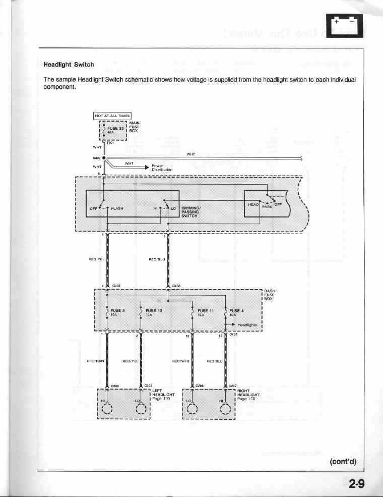
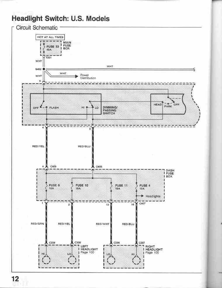
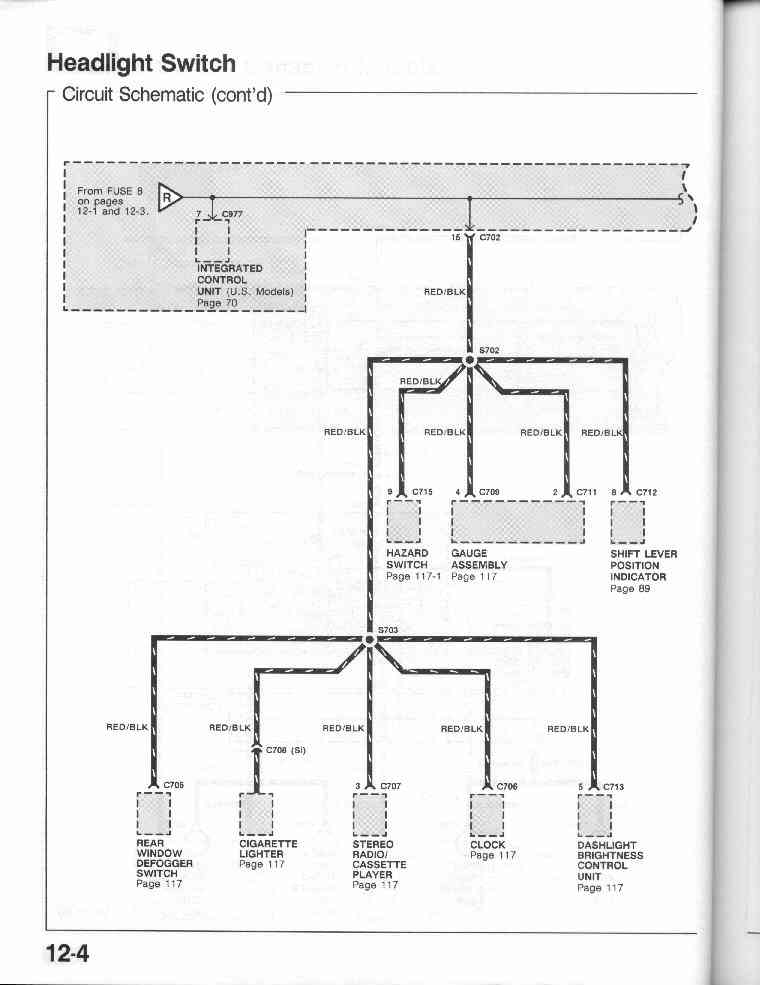
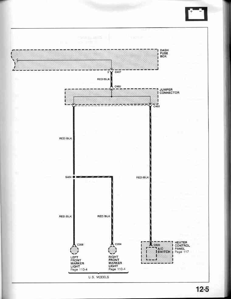
12-0 Headlight Switch (U.S. Models) Circuit
Schematic
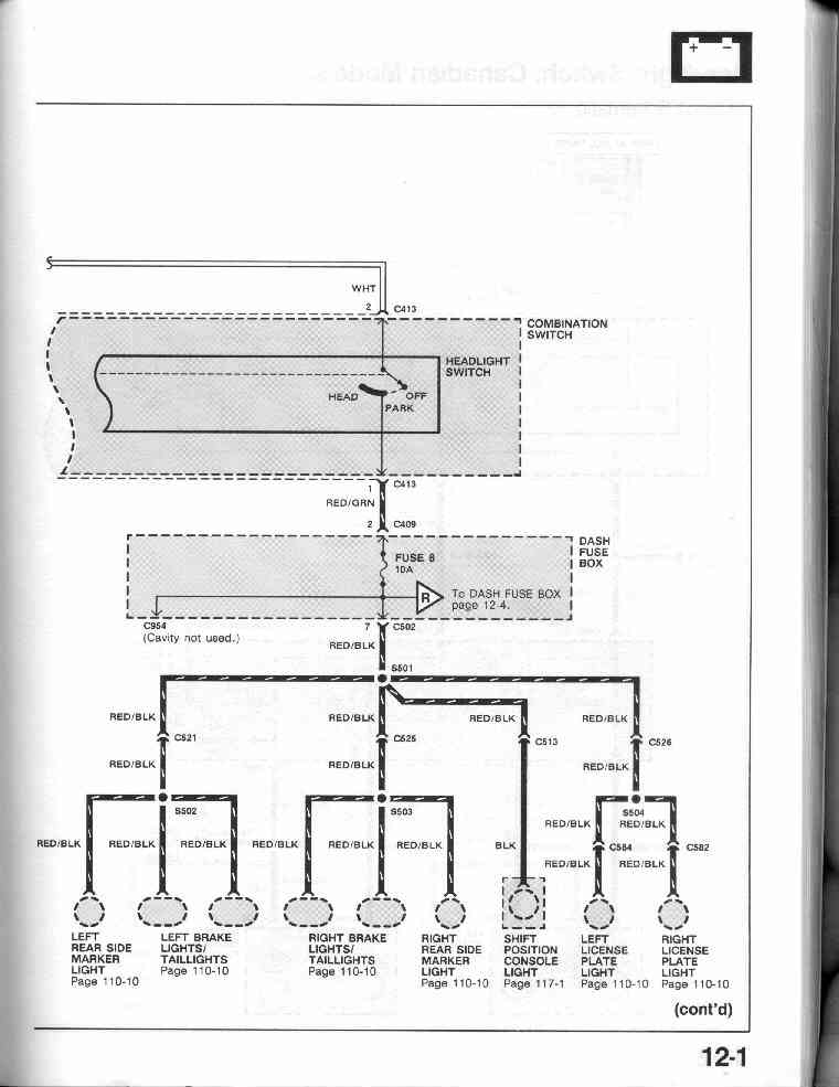
12-1
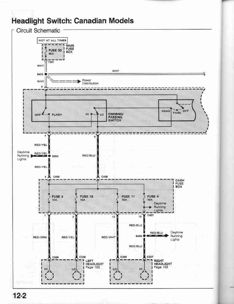
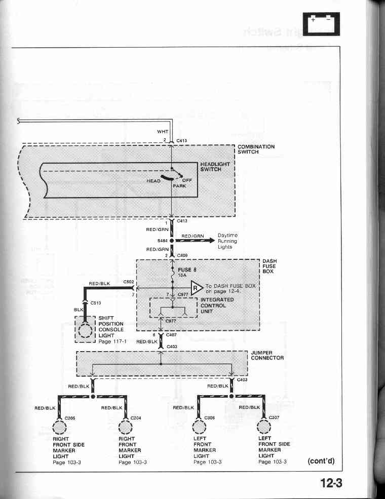
12-2 Headlight Switch (Canadian Model) Circuit Schematic
12-3, 12-4, 12-5
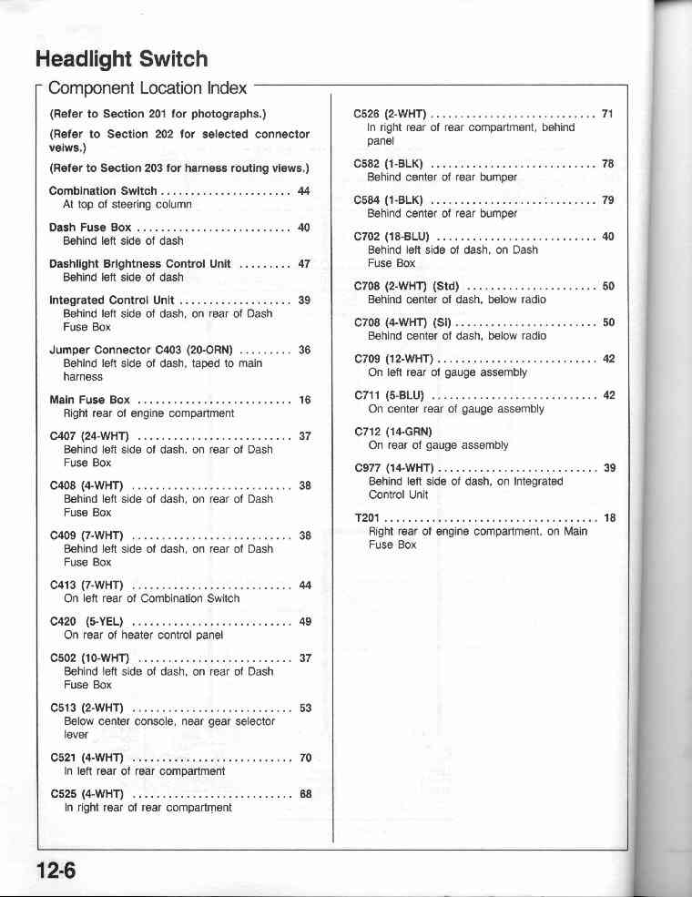
12-6 Headlight Switch Component Location Index
14-0
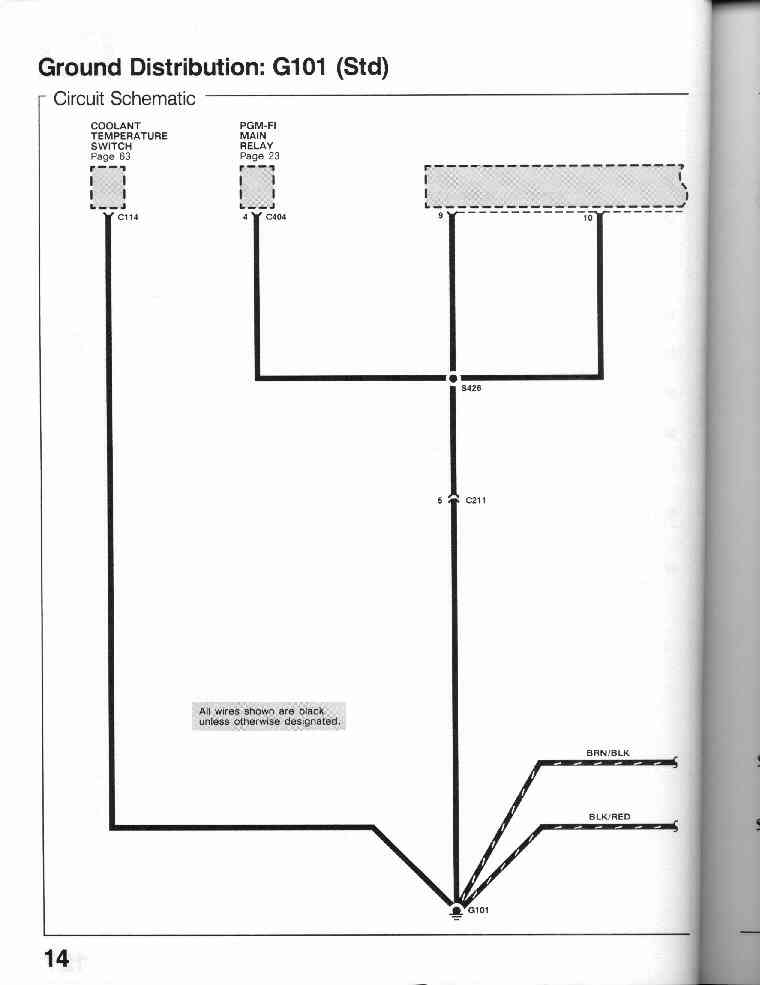
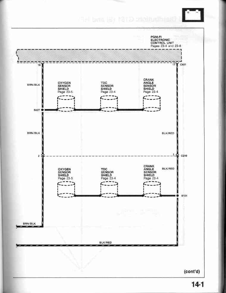
Ground Distribution: G101 (Std and DX)
14-1
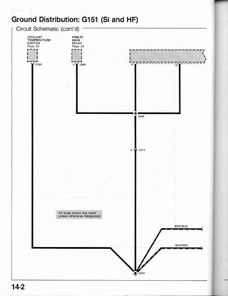
14-2 Ground Distribution: G151 (Si and HF)
14-3
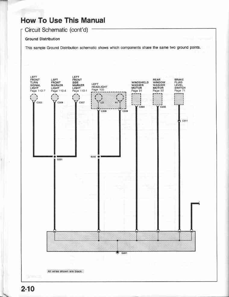
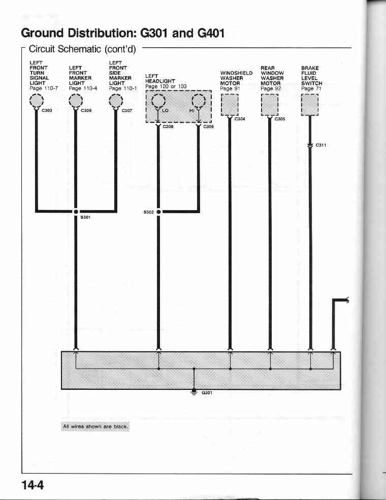
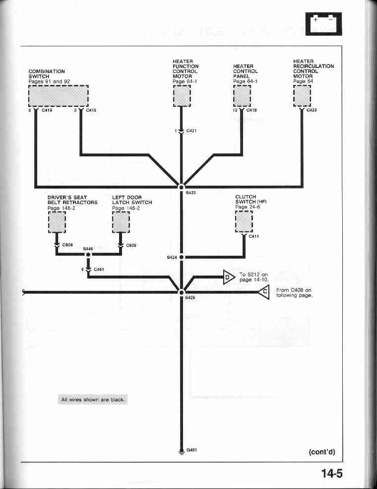
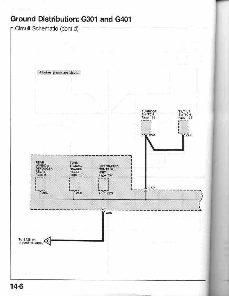
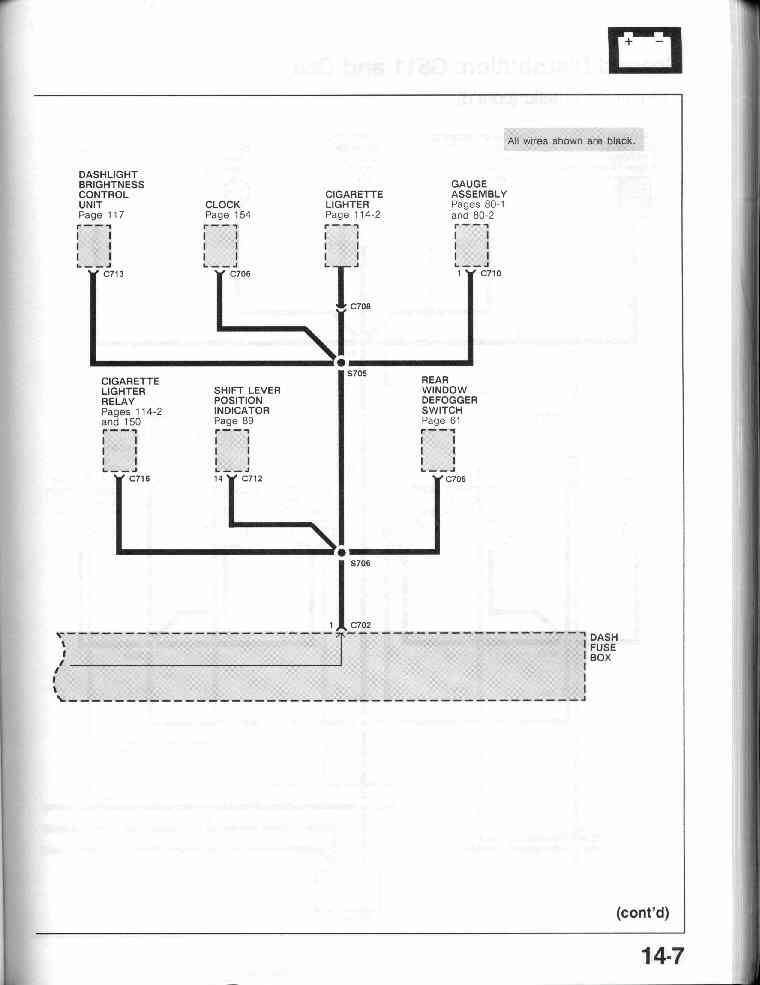
14-4 Ground Distribution: G301 and G401
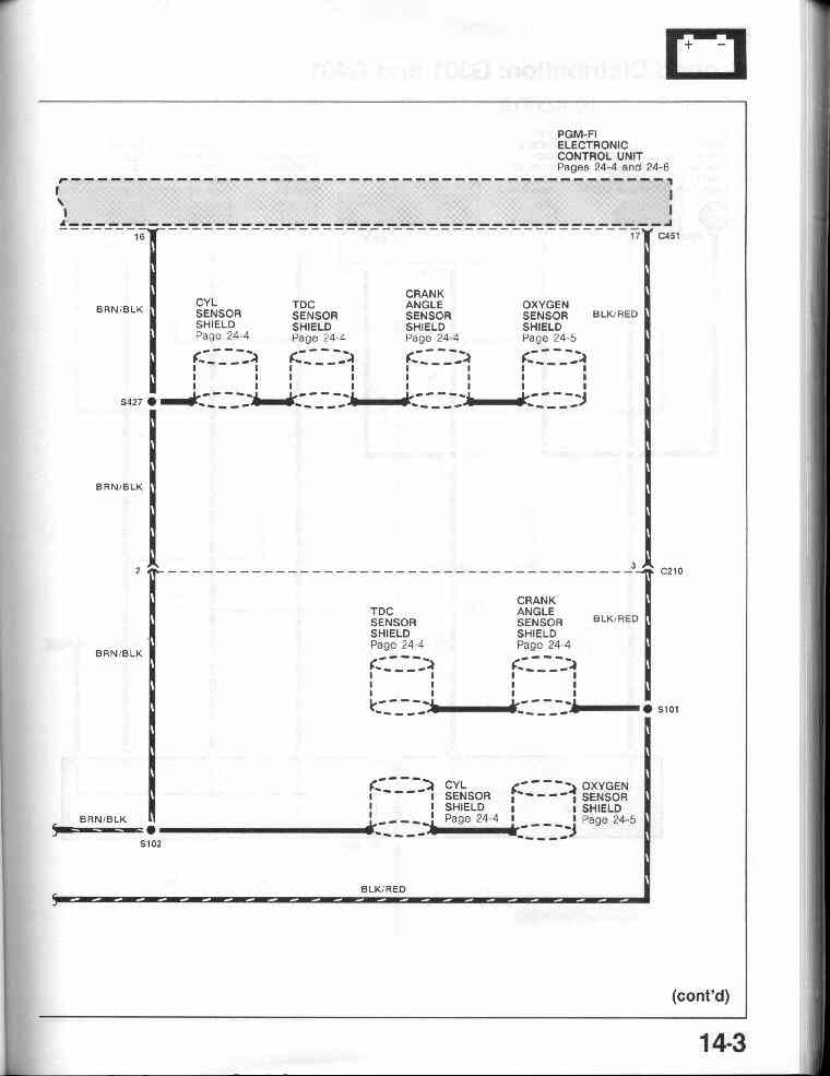
14-5, 14-6,
14-7
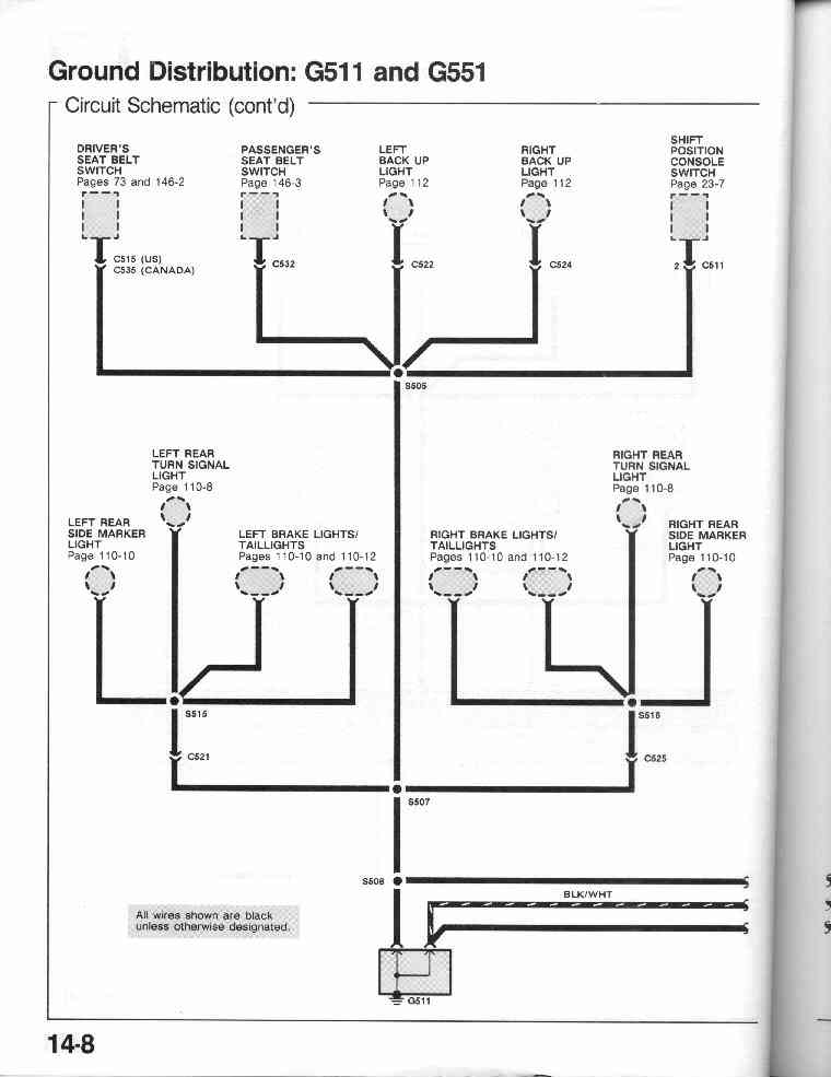
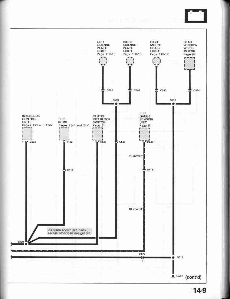
14-8 Ground Distribution: G511 and G551
14-9
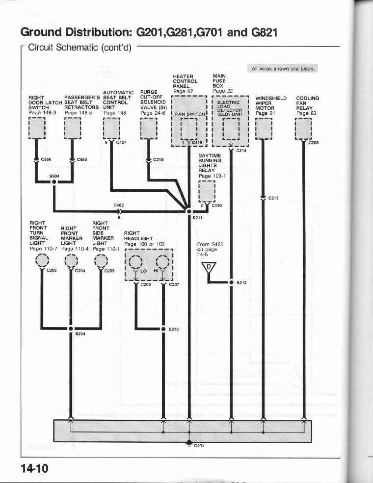
14-10 Ground Distribution: G201, G281, G701 and G821
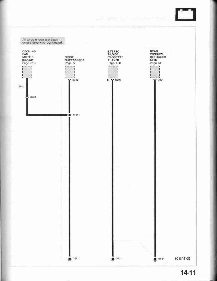
14-11
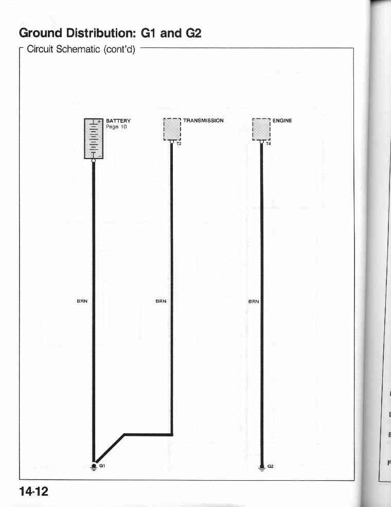
14-12 Ground Distribution: G1 and G2
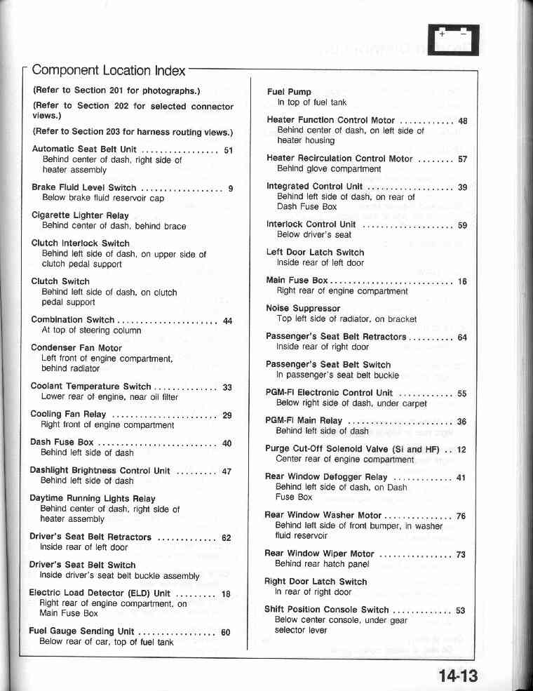
14-13 Ground Component Location Index
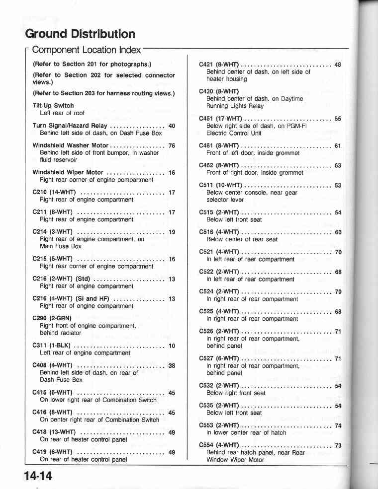
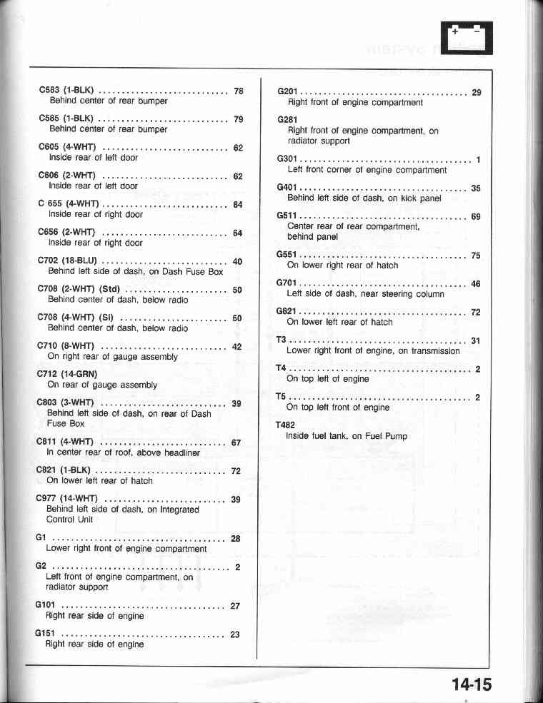
14-14, 14-15
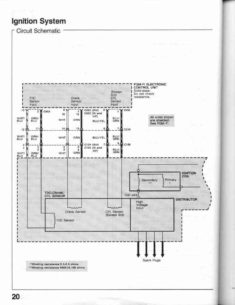
20-0 Ignition System (Circuit Schematic)
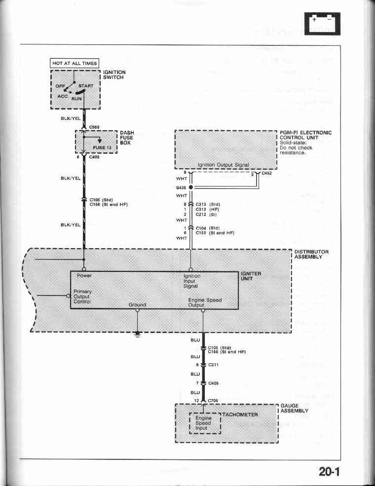
20-1
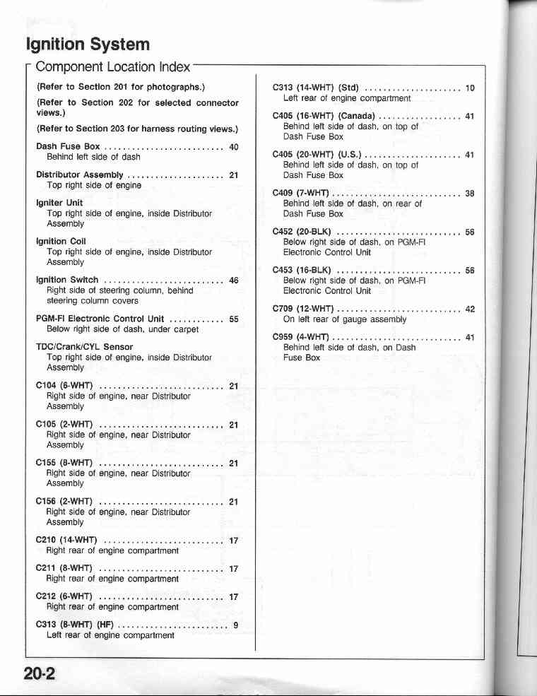
20-2 Ignition System Component Location Index
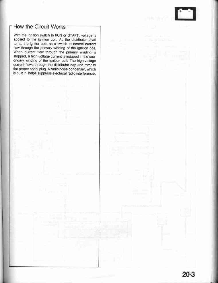
20-3 Ignition System - How the circuit works
21-0
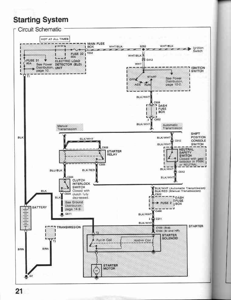
Starting System Circuit Schematic (diagram)
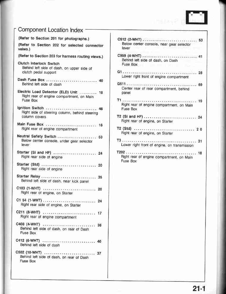
21-1 Starting System Component Location Index
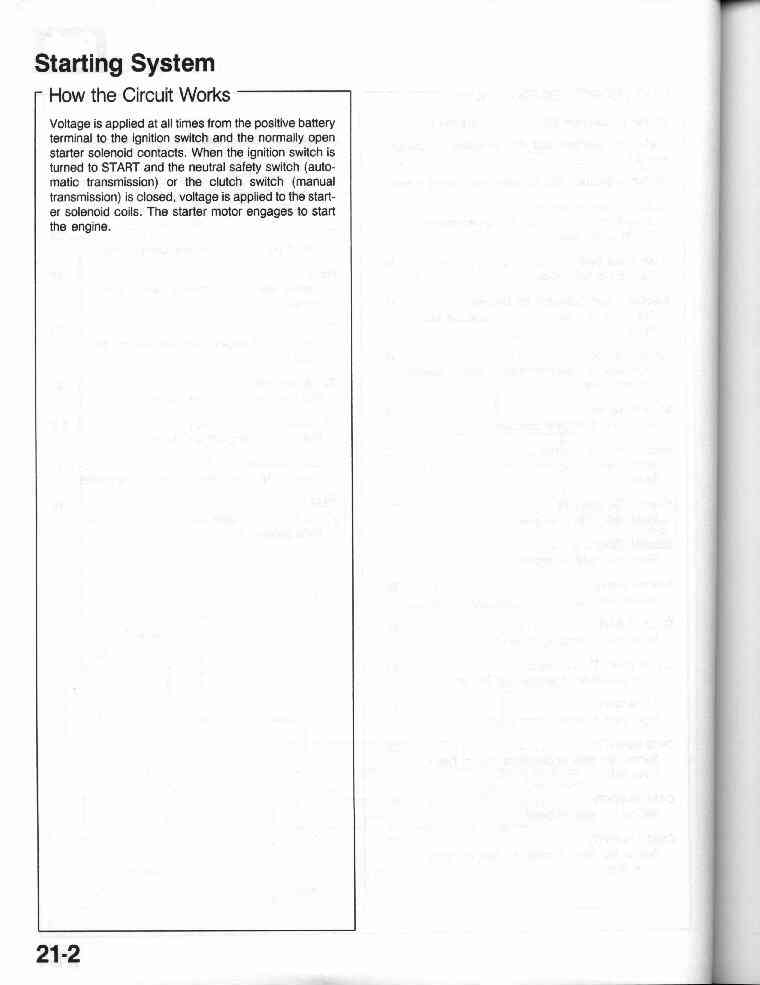
21-2 Starting System - How the circuit works
22-0
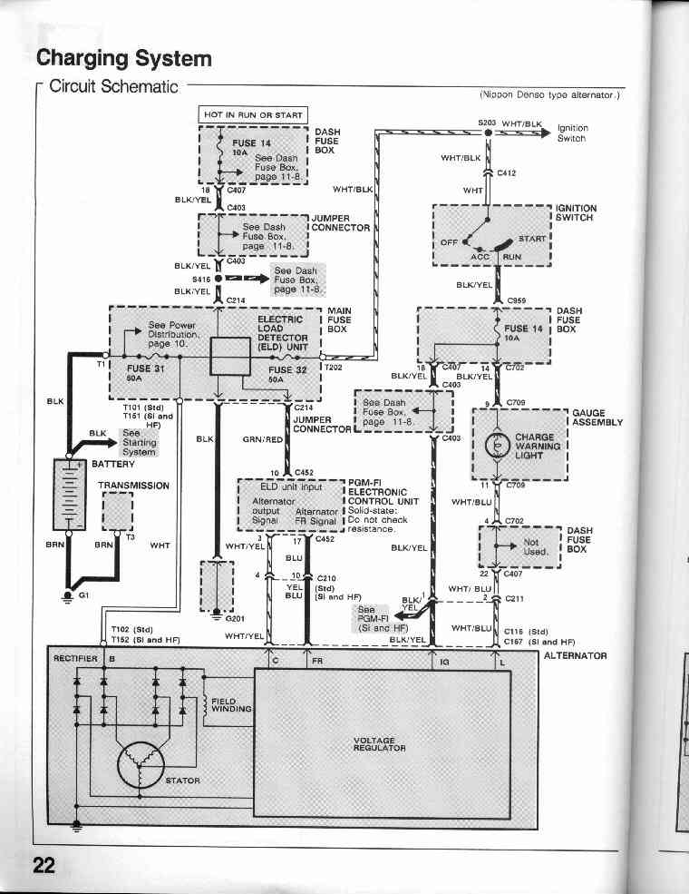
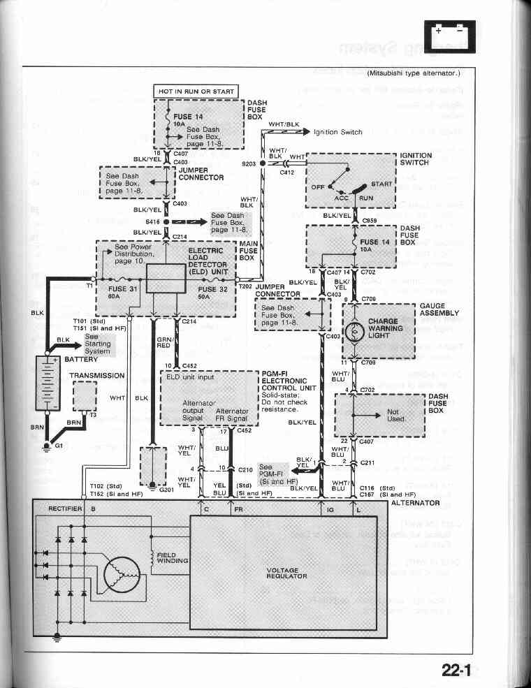
Charging System Circuit Schematic (diagram)
22-1
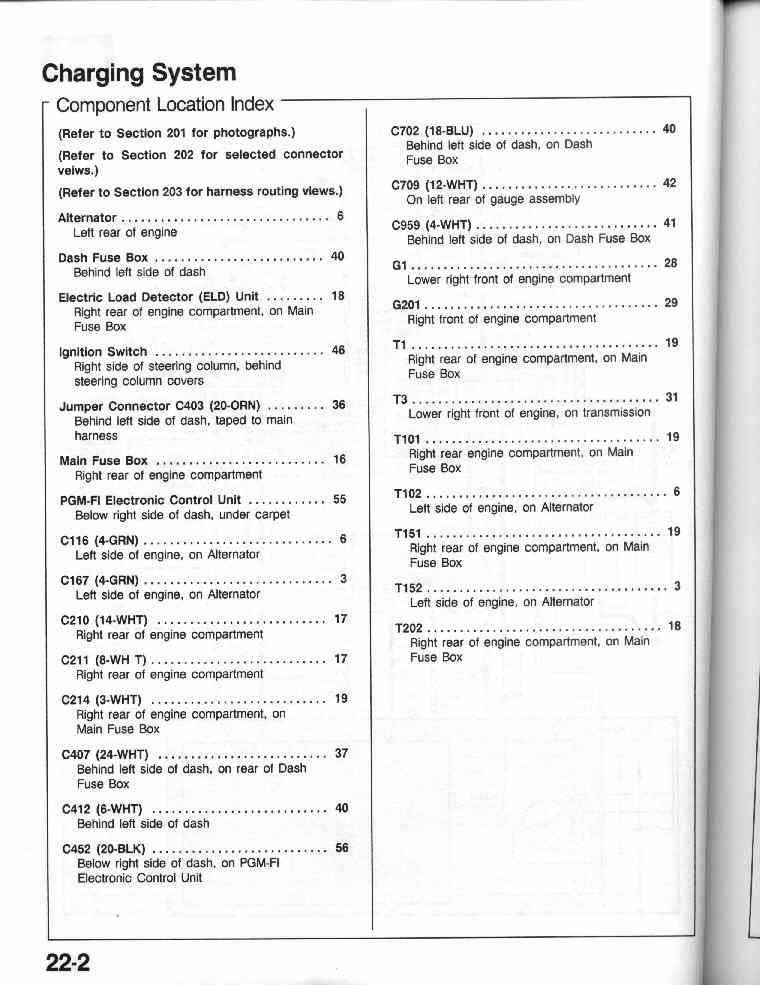
22-2 Charging System Component Location Index
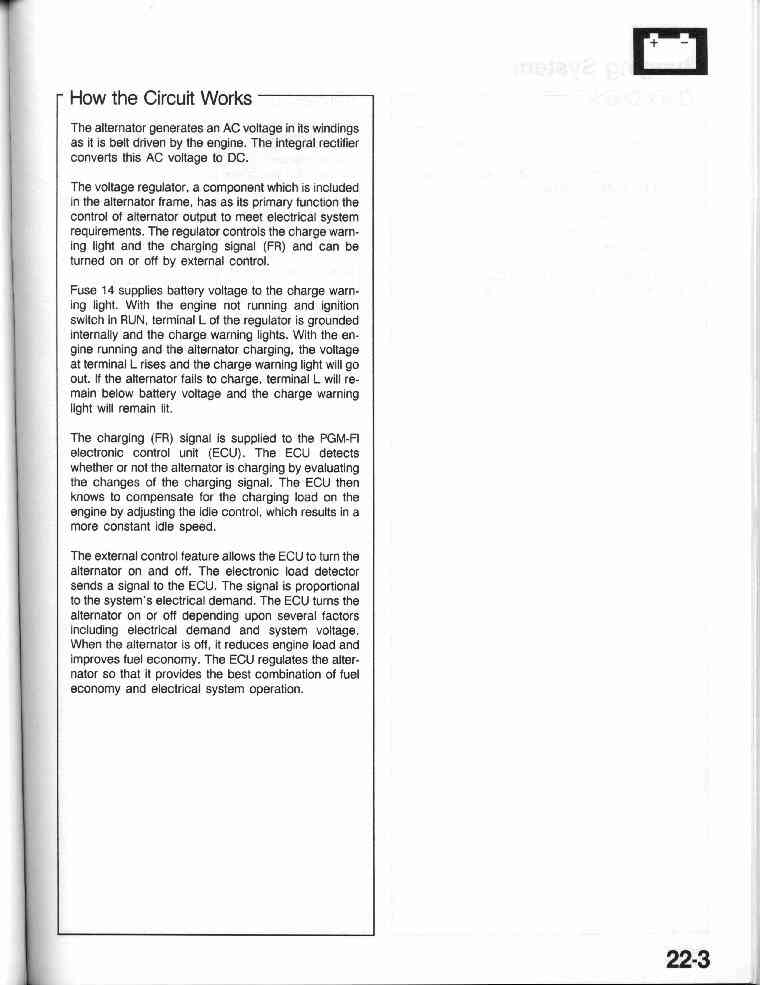
22-3 Charging System - How the circuit works
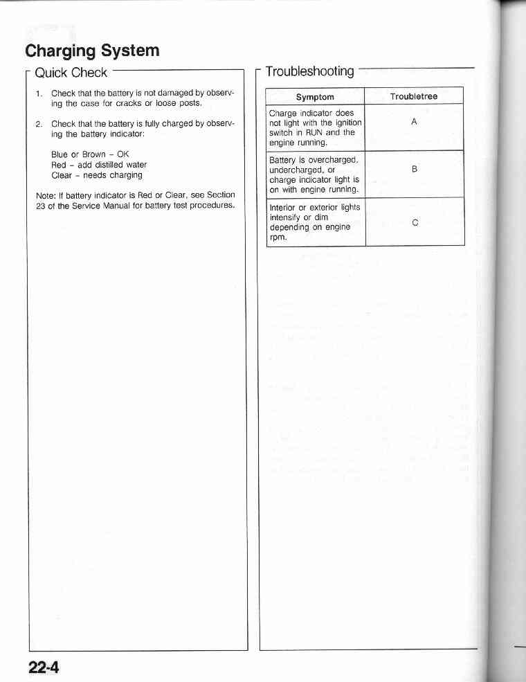
22-4 Charging System - Quick Check
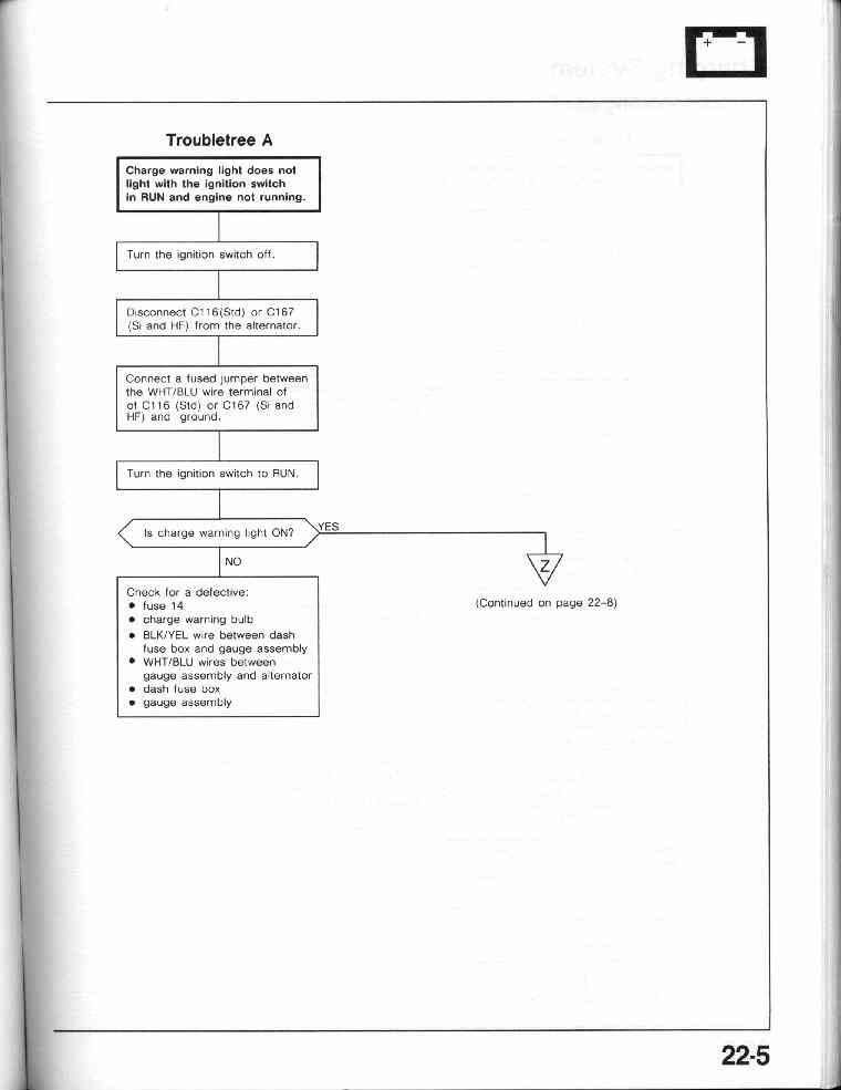
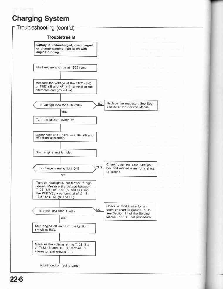
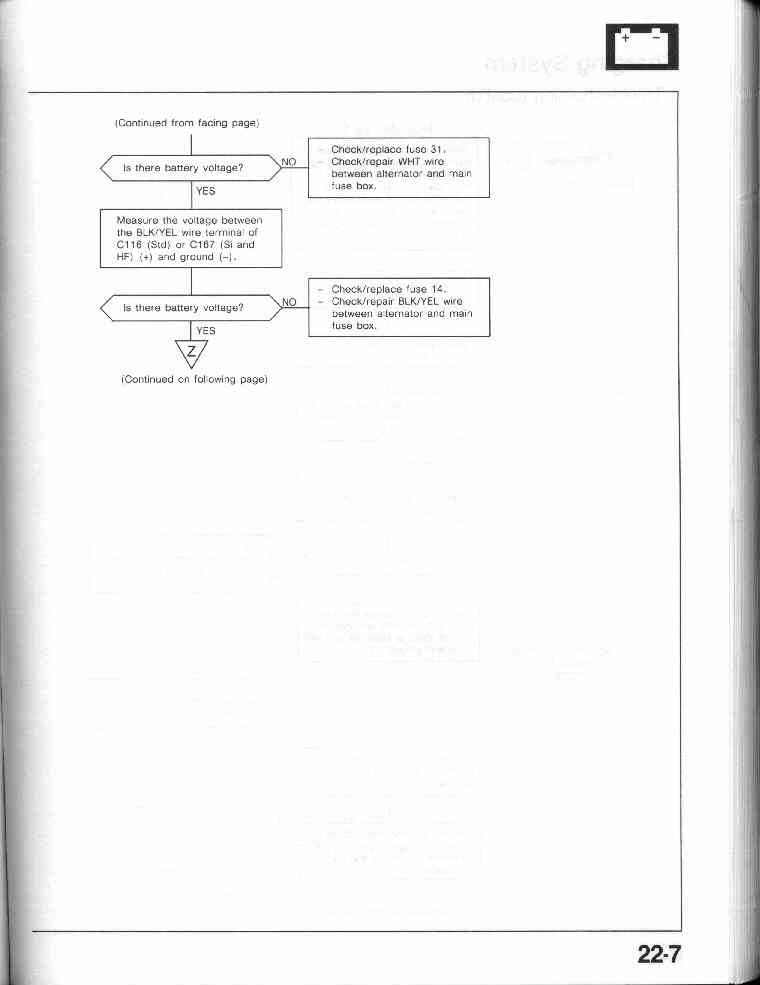
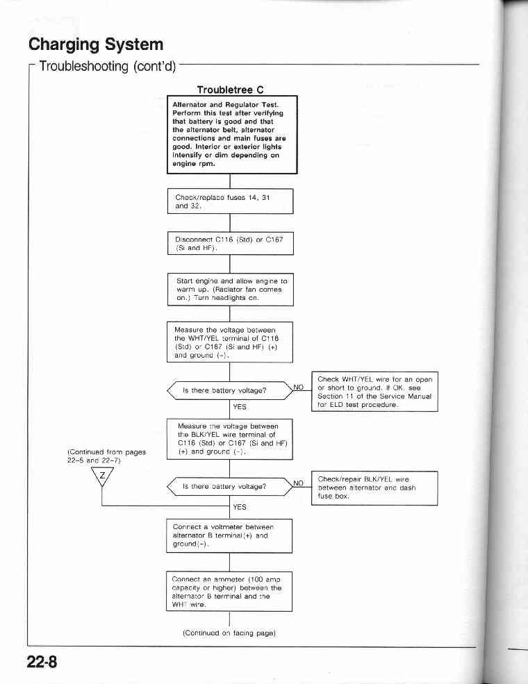
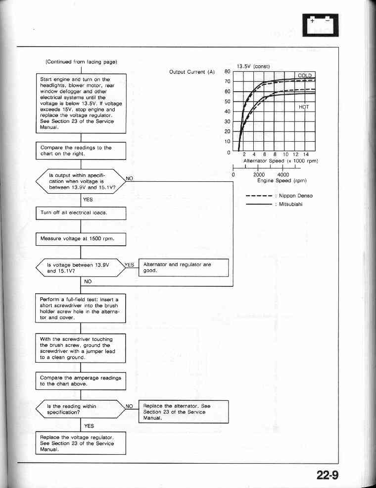
22-4 Charging System - Troubleshooting Tree
22-5, 22-6,
22-7, 22-8,
22-9
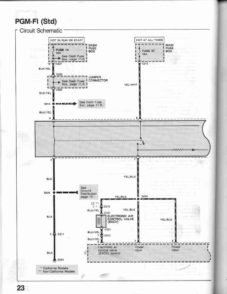
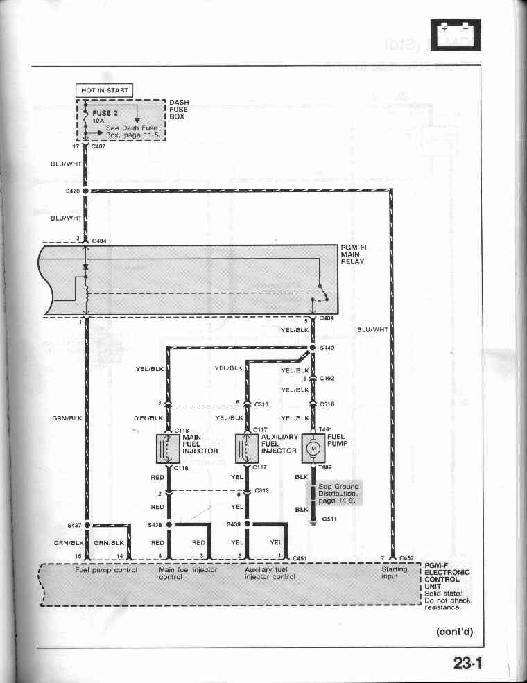
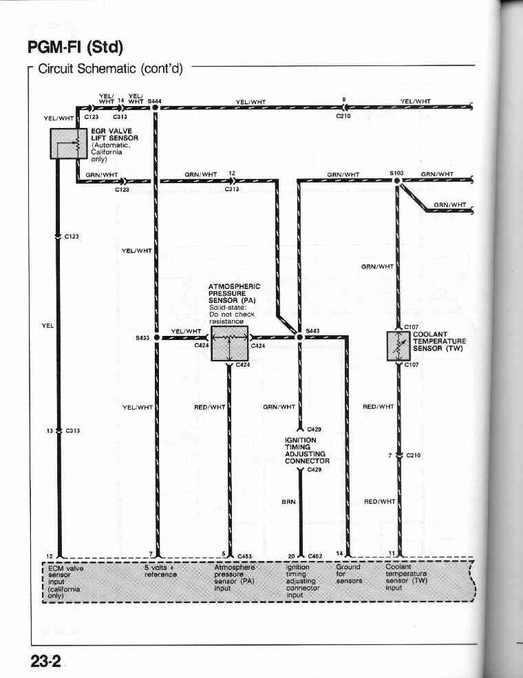
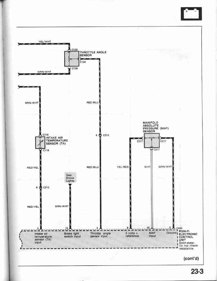
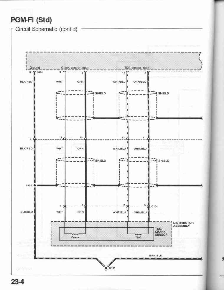
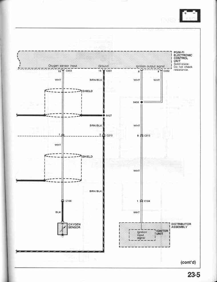
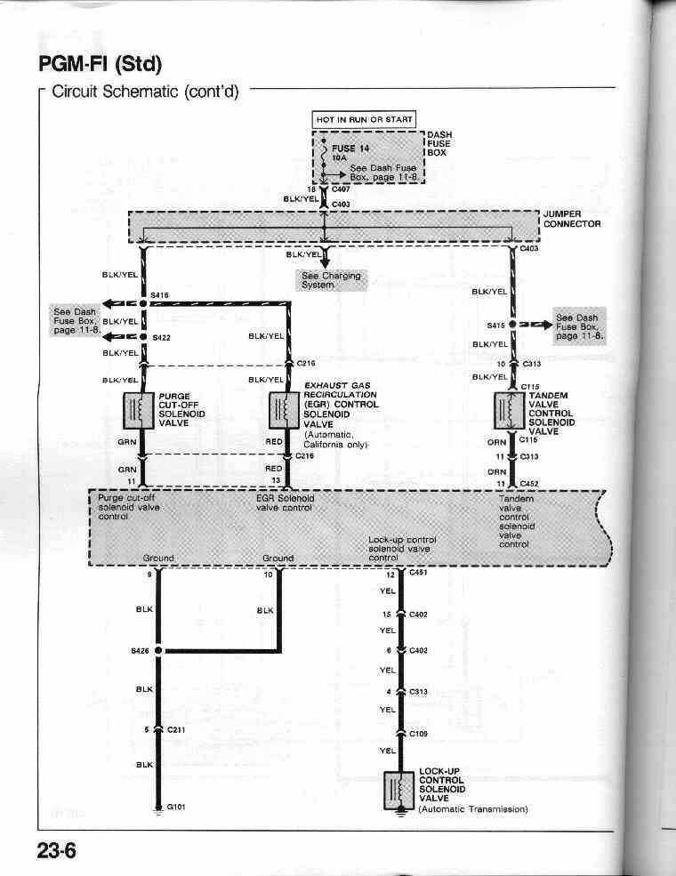
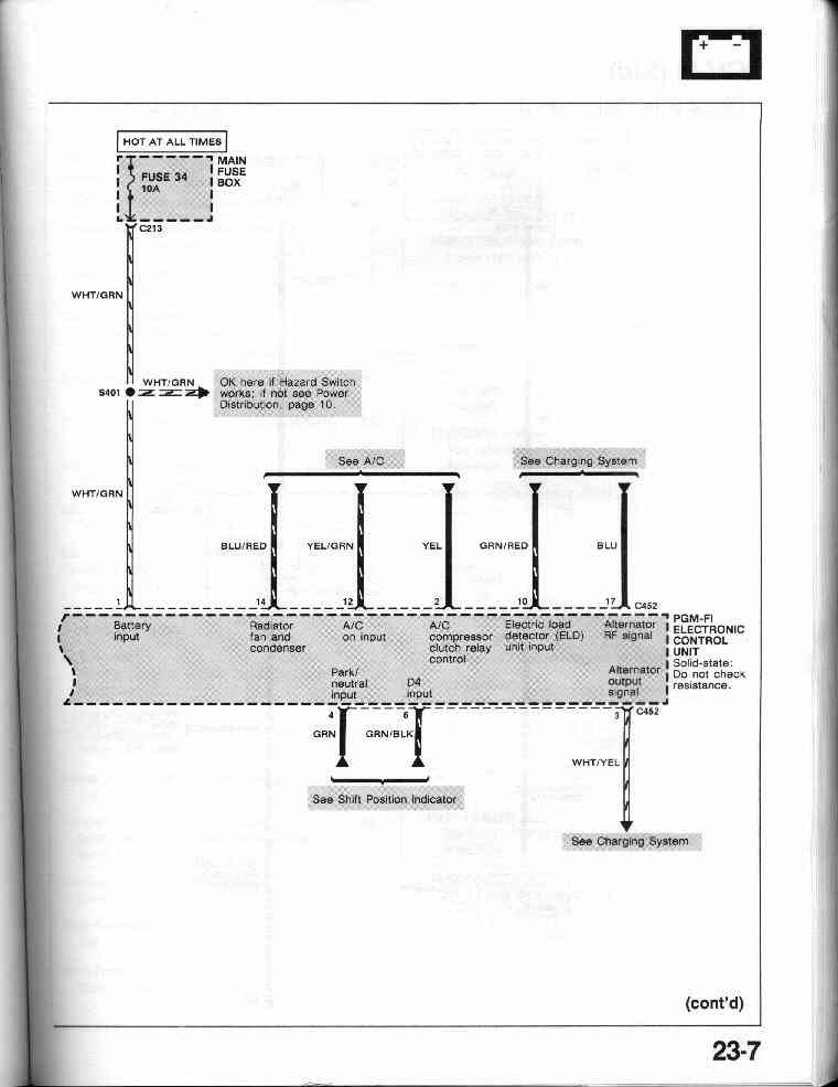
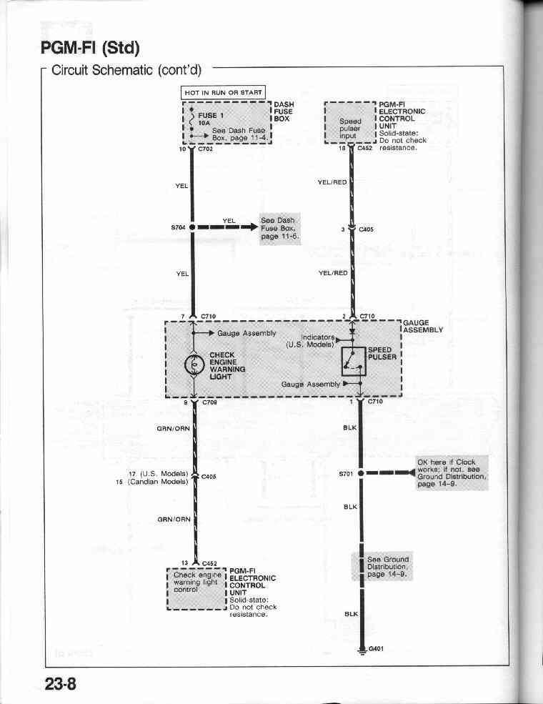
23-0 PGM-FI Circuit Schematic
(Std and DX) - DPFI
23-1, 23-2, 23-3,
23-4, 23-5, 23-6,
23-7, 23-8
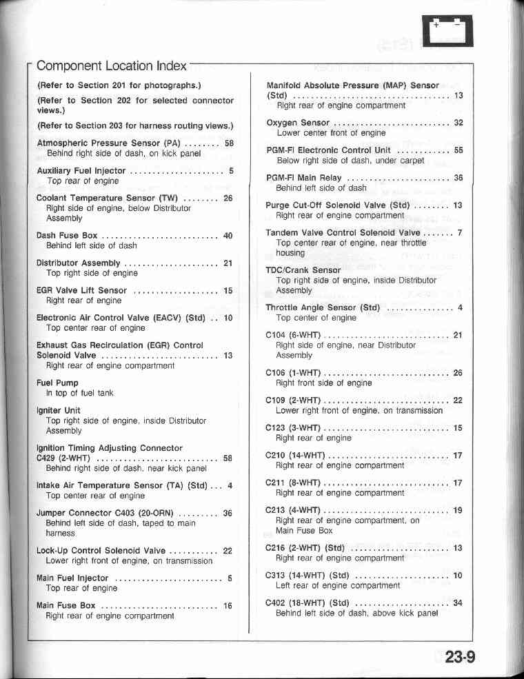
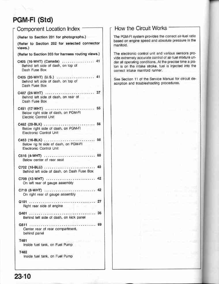
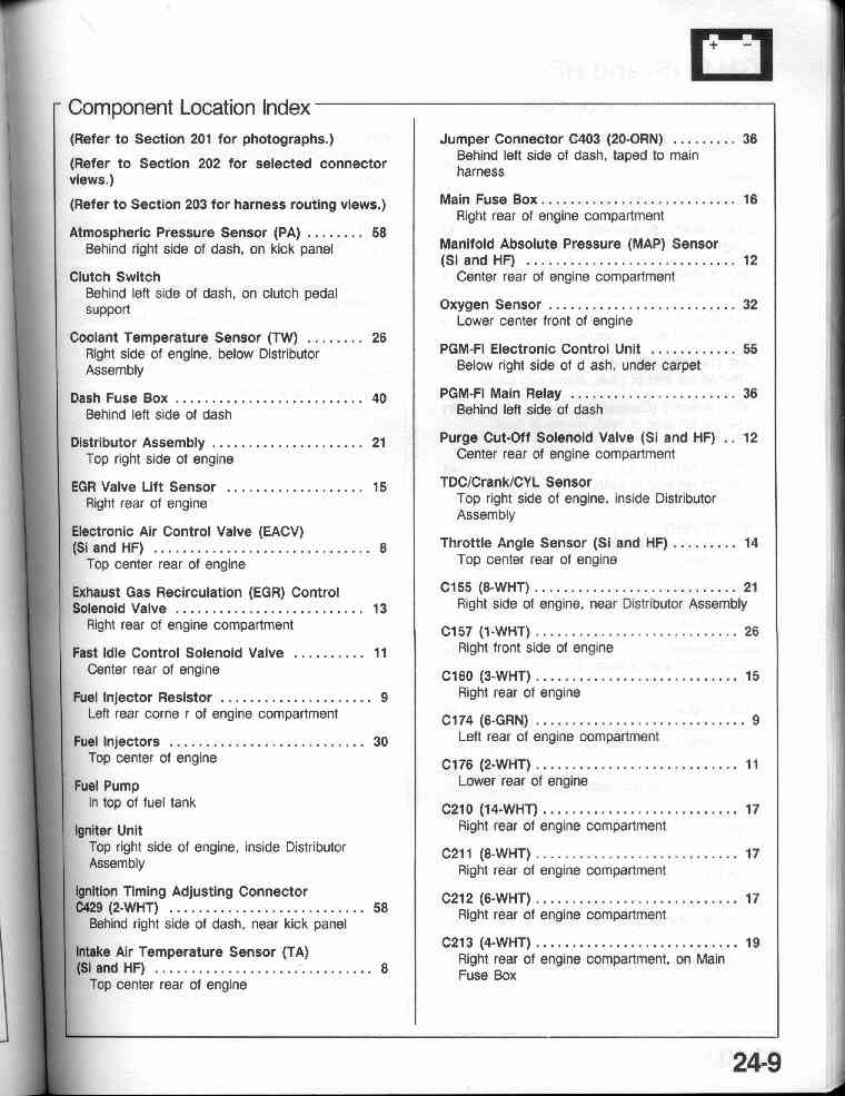
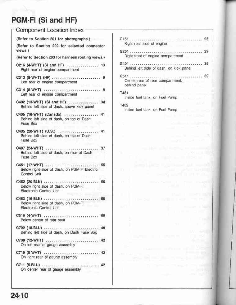
23-9 PGM-FI Component Location Index
23-10
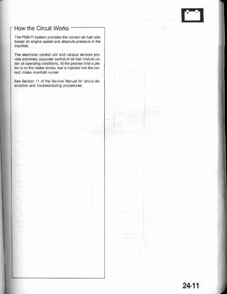
23-10 PGM-FI - How the circuit works
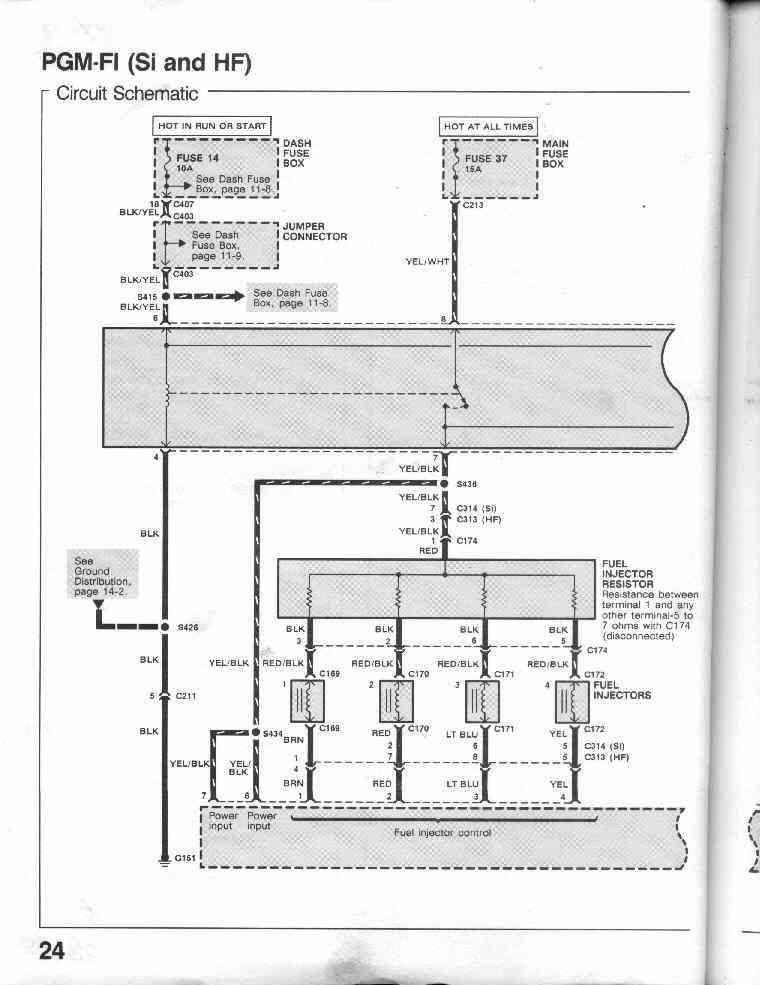
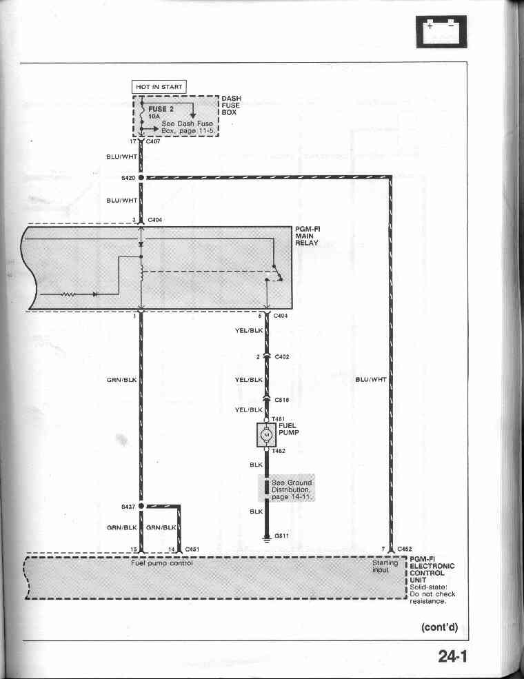
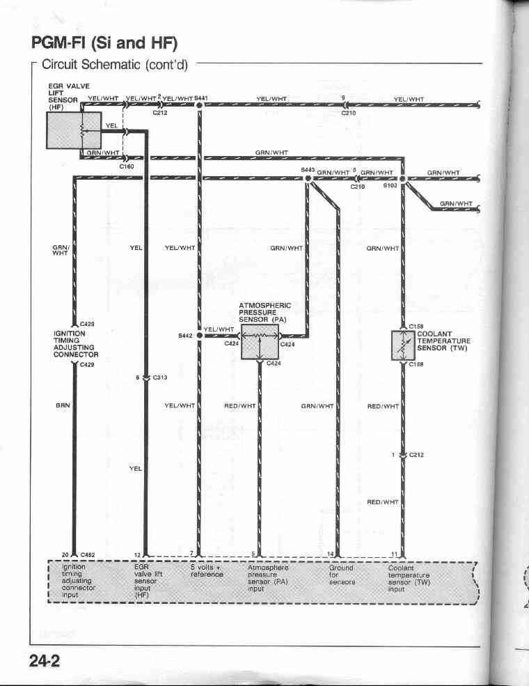
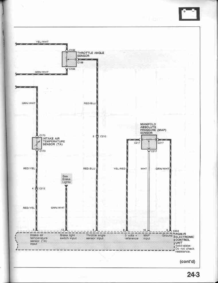
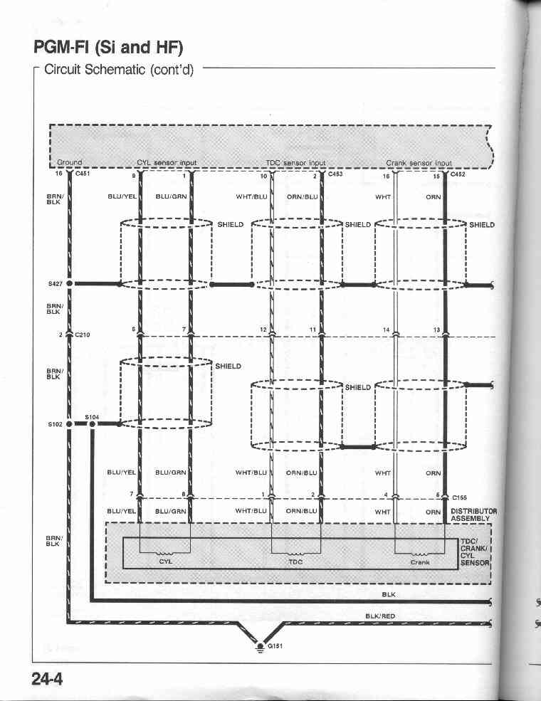
24-0
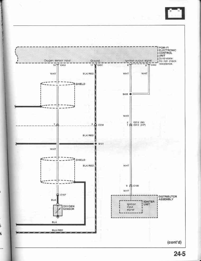
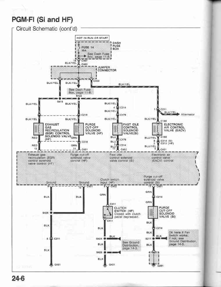
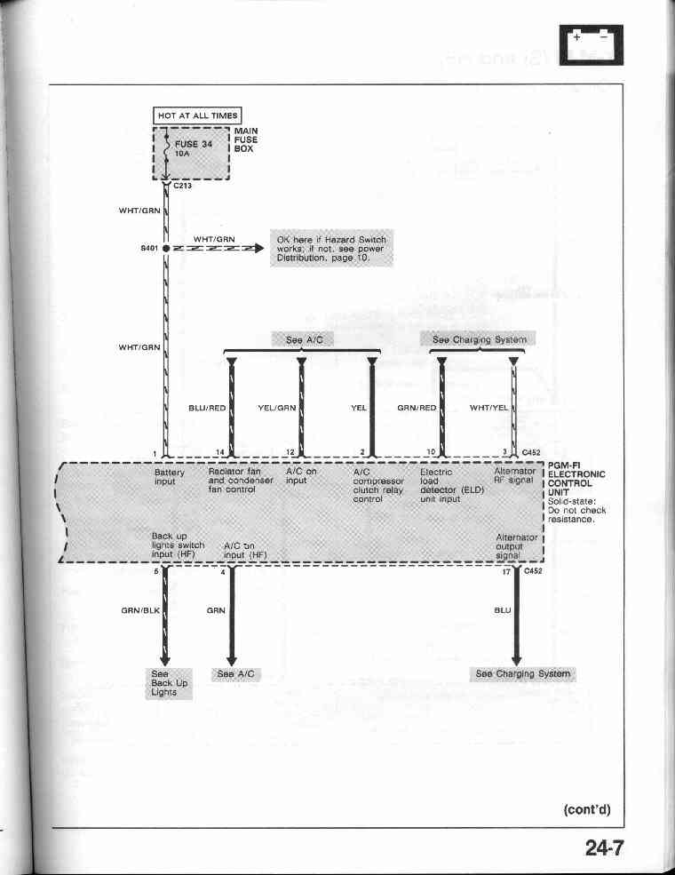
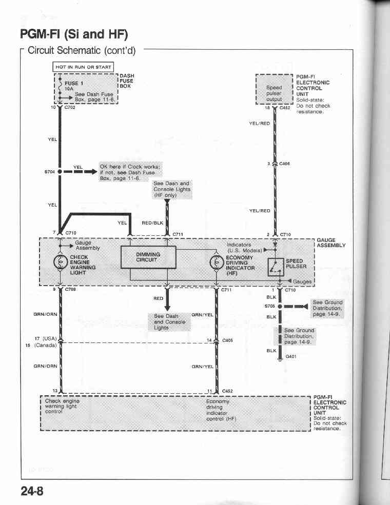
PGM-FI Circuit Schematic (Si and HF) - MPFI
24-1, 24-2, 24-3,
24-4, 24-5,
24-6, 24-7,
24-8
24-9 PGM-FI Component Location Index
24-10
24-11 PGM-FI - How the circuit works
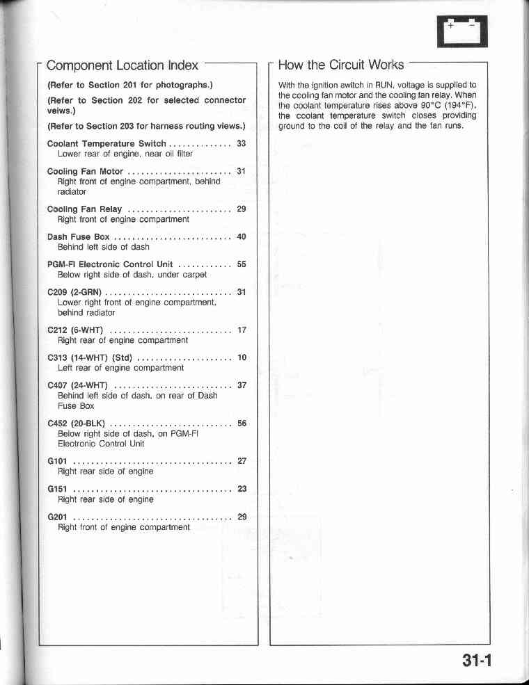
31-0
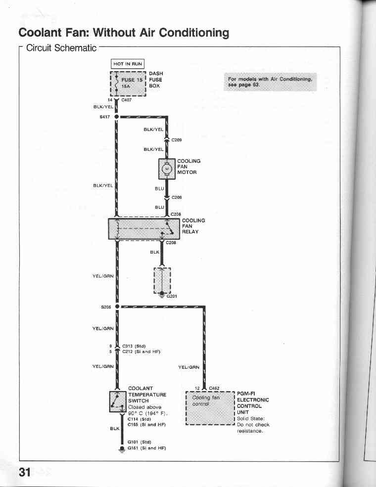
Coolant Fan: Without Air Conditioning - Circuit Diagram
31-1 Coolant Fan: Without Air Conditioning - Component
Location Index
31-1 Coolant Fan: Without Air Conditioning - How the
circuit works
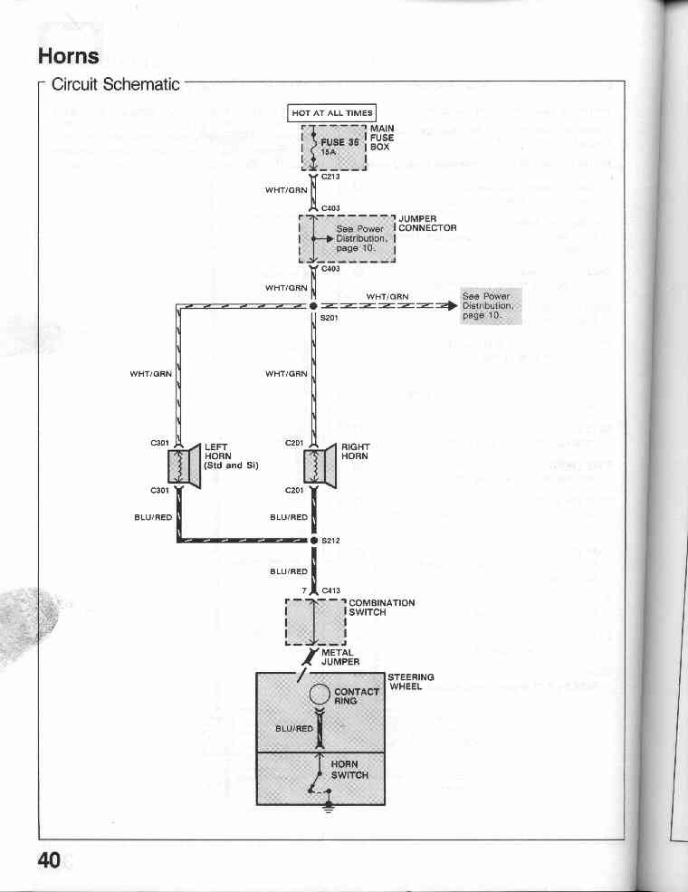
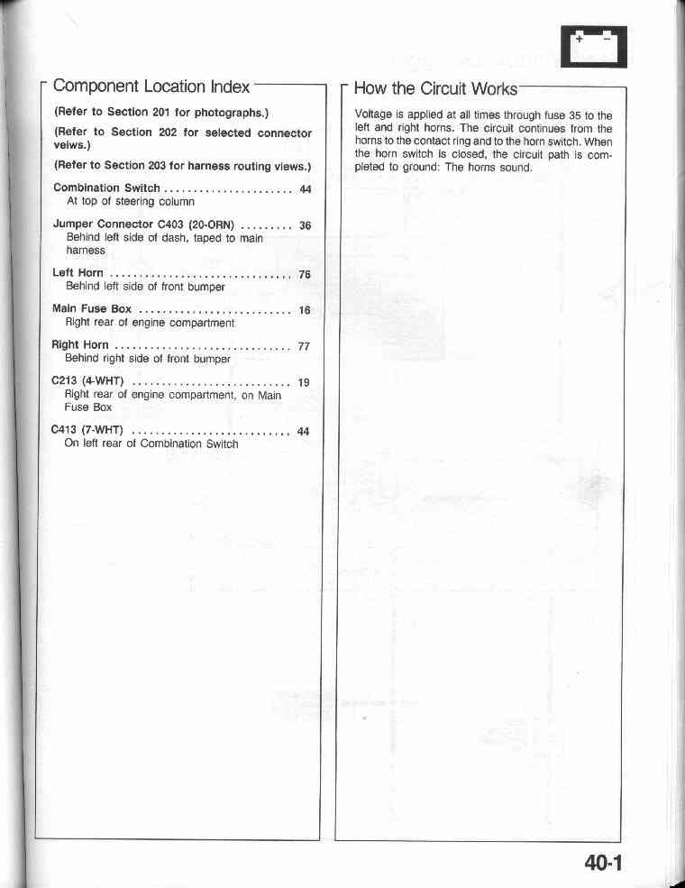
40-0 Horns - Circuit Diagram
40-1 Horns - Component Location Index
40-1 Horns - How the circuit works
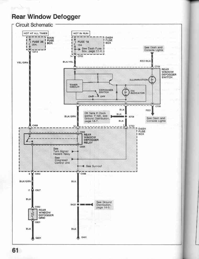
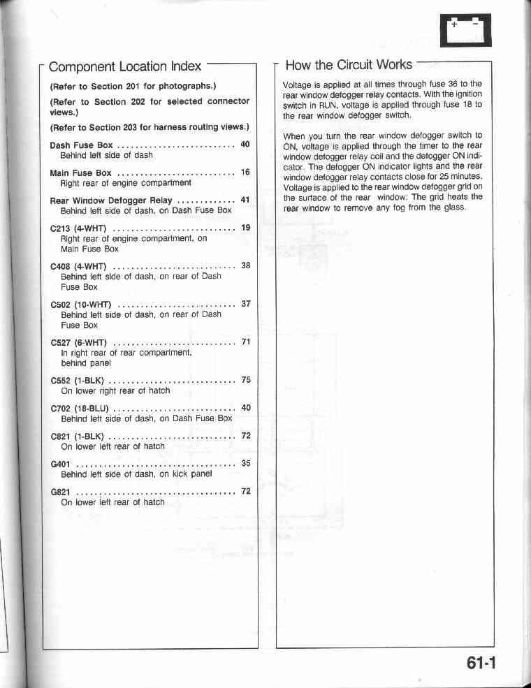
61-0
Rear Windows Defogger - Circuit Diagram
61-1 Rear Windows Defogger - Component Location Index
61-1 Rear Windows Defogger - How the circuit works
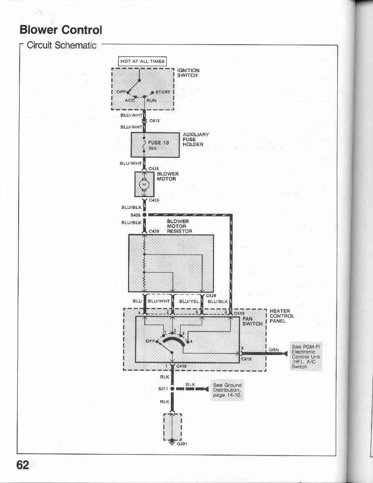
62-0
Blower Control - Circuit Diagram
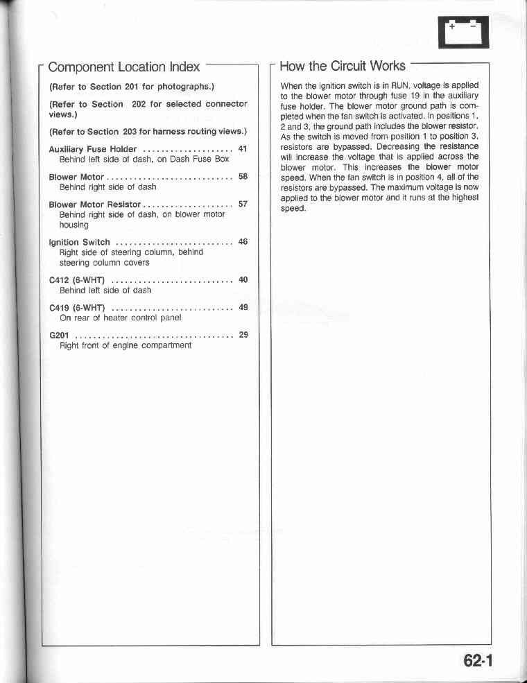
62-1 Blower Control - Component Location Index
62-1 Blower Control - How the circuit works
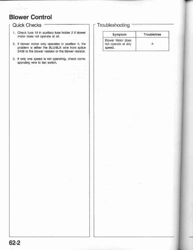
62-2 Blower Control - Quick Checks
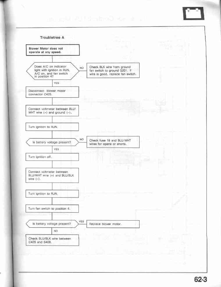
62-2 Blower Control - Troubleshooting Tree
62-3
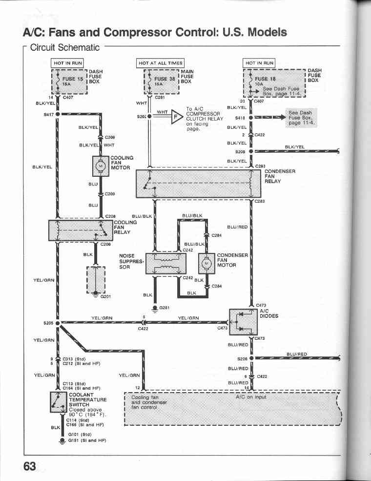
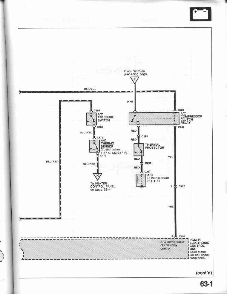
63-0 A/C: Fans and Compressor Control: US Model -
Circuit Diagram
63-1
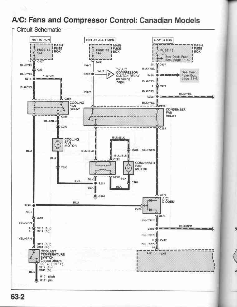
63-2 A/C: Fans and Compressor Control: Canadian Model -
Circuit Diagram
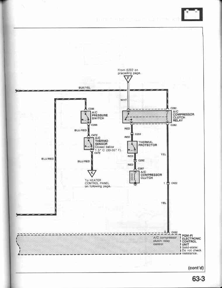
63-3
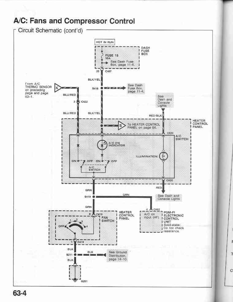
63-4 A/C: Fans and Compressor Control - Circuit Diagram
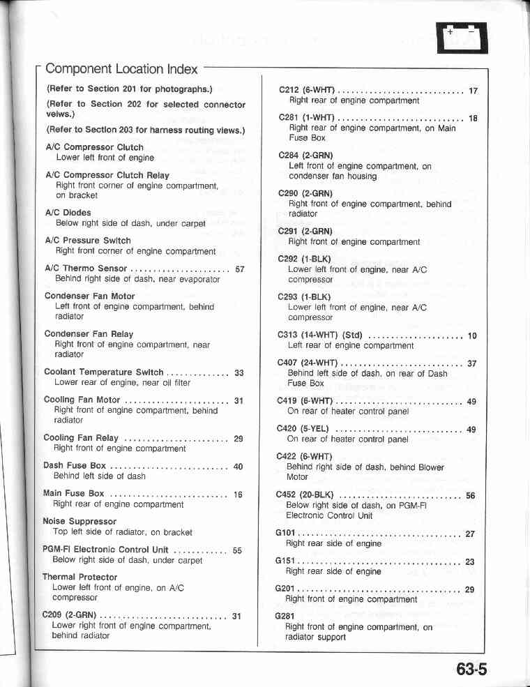
63-5 A/C: Fans and Compressor Control - Component Location
Index
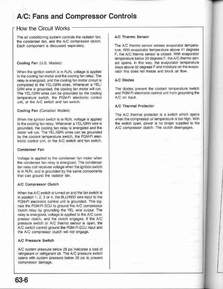
63-6 A/C: Fans and Compressor Control - How the circuit works
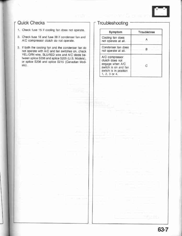
63-7 A/C: Fans and Compressor Control - Quick Checks
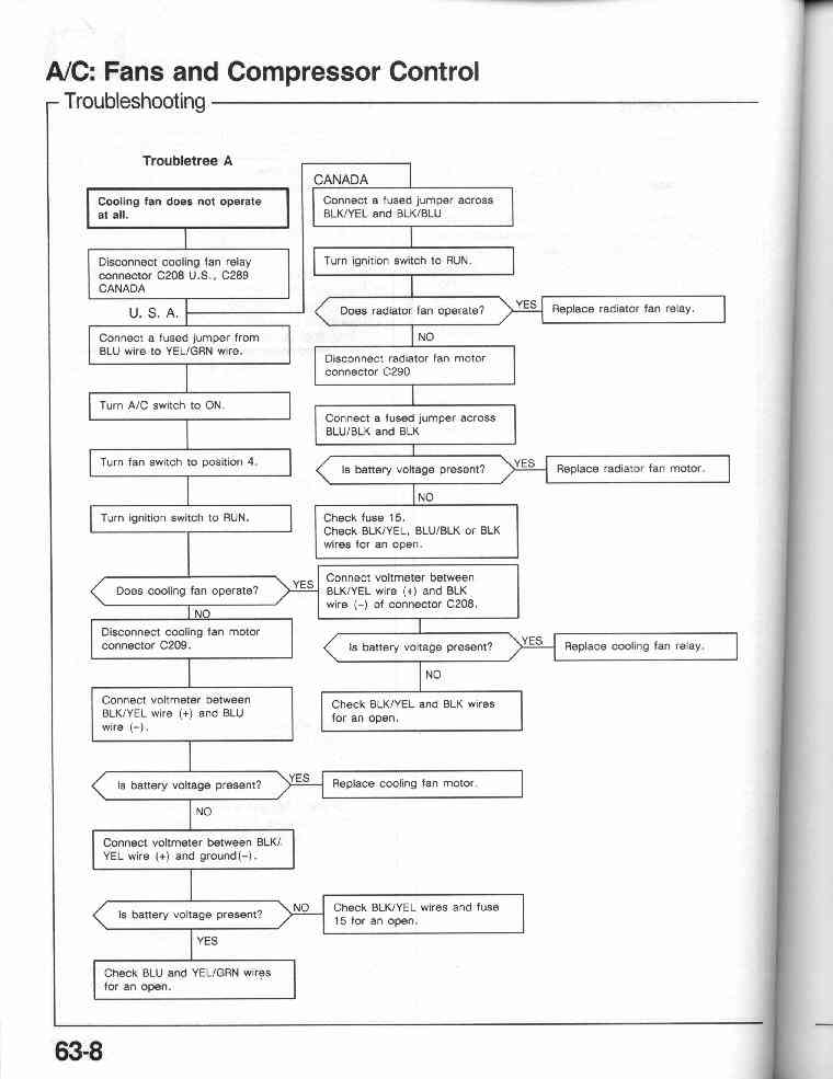
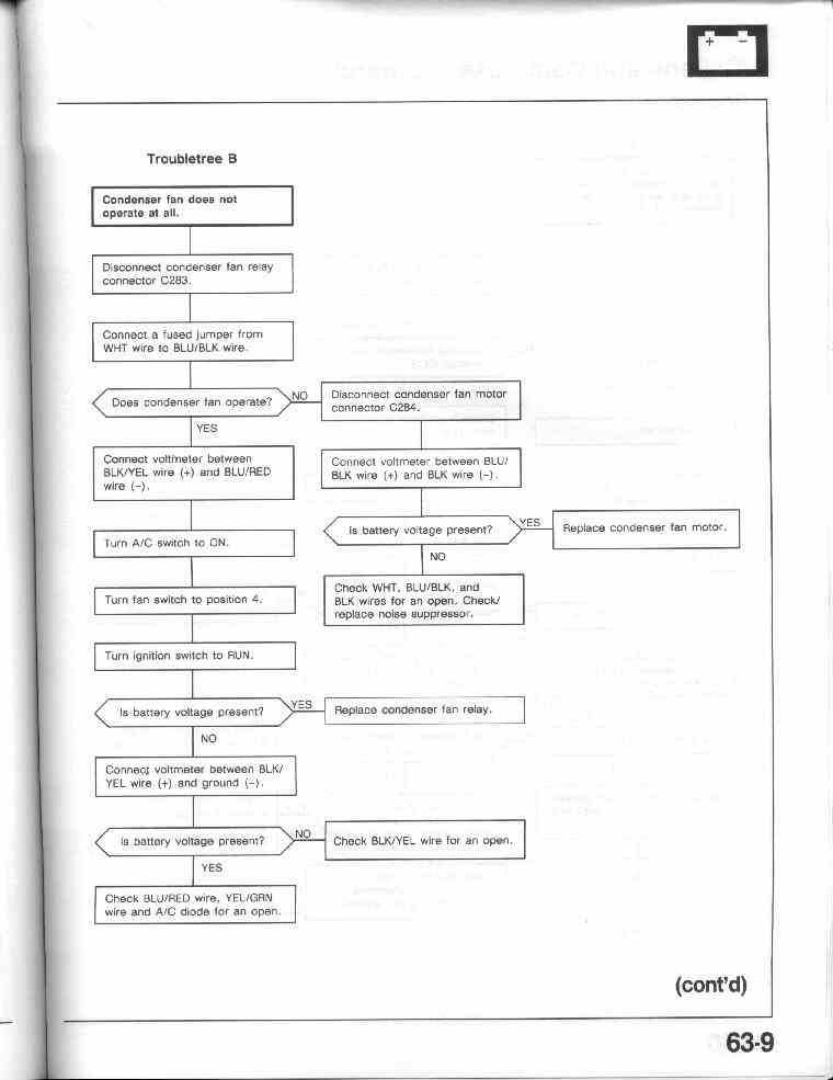
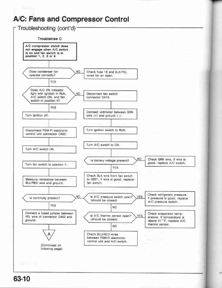
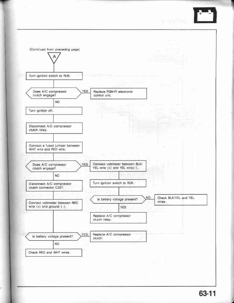
63-7 A/C: Fans and Compressor Control - Troubleshooting Tree
63-8, 63-9,
63-10, 63-11
![]()
THE FOLLOWING ARE NOT CURRENTLY ONLINE
64-0 A/C: Air Delivery - Circuit
Diagram
64-1
64-2 A/C: Air Delivery - Component Location Index
64-2 A/C: Air Delivery - How the circuit works
70-0
Integrated Control Unit - Circuit Diagram
70-1
70-2 Integrated Control Unit - Component Location Index
70-2 Integrated Control Unit - How the circuit works
71-0
Brake Warning System - Circuit Schematic
71-1 Brake Warning System - Component Location Index
71-1 Brake Warning System - How the circuit works
72-0
Oil Pressure Warning System - Circuit Diagram
72-1 Oil Pressure Warning System - Component Location Index
72-1 Oil Pressure Warning System - How the circuit works
73-1
Seat Belt and Key-on Warning System - Circuit Diagram
73-1
73-2 Seat Belt and Key-on Warning System - Component Location
Index
73-3 Seat Belt and Key-on Warning System - How the circuit
works
80-0 Indicators (Dash Lamps) - Circuit Schematic
80-1, 80-2, 80-3
80-4 Indicators (Dash Lamps) - Component Location Index
80-4 Indicators (Dash Lamps) - How the circuit works
81-0
Gauges - Circuit Schematic
81-1 Gauges - Component Location Index
81-1 Gauges - How the circuit works
89-0
Shift Position Indicator - Circuit Schematic
89-1 Shift Position Indicator - Component Location Index
89-1 Shift Position Indicator - How the circuit works
91-0
Wiper/Washer - Circuit Schematic
91-1 Wiper/Washer - Component Location Index
91-1 Wiper/Washer - How the circuit works
92-0
Rear Wiper/Washer - Circuit Diagram
92-1 Rear Wiper/Washer - Component Location Index
92-1 Rear Wiper/Washer - How the circuit works
100-0
Headlights - Circuit Diagrams
100-1 Headlights - Component Location Index
100-1 Headlights - How the circuit works
103-0
Daytime Running Lights: Canadian Models - Circuit Diagram
103-1, 103-2, 103-3
103-4 Daytime Running Lights: Canadian Models - Component
Location Index
103-5 Daytime Running Lights: Canadian Models - How the
circuit works
110-0 Front Side Marker Lights - Circuit
Schematic
110-1
110-2 Front Side Marker Lights - Component Location Index
110-2 Front Side Marker Lights - How the circuit works
110-4
Front Marker Lights - Circuit Schematic
110-5 Front Marker Lights - Component Location Index
110-5 Front Marker Lights - How the circuit works
110-6
Turn Signal and Hazard Lights - Circuit Schematic
110-7, 110-8
110-9 Turn Signal and Hazard Lights - Component Location Index
110-9 Turn Signal and Hazard Lights - How the circuit works
110-10
Tail, Rear Side Marker and License Plate Lights - Circuit Schematic
110-11 Tail, Rear Side Marker and License Plate Lights -
Component Location Index
110-11 Tail, Rear Side Marker and License Plate Lights - How
the circuit works
110-12 Brake Lights - Circuit Schematic
110-13 Brake Lights - Component Location Index
110-13 Brake Lights - How the circuit work
112-0
Back Up Lights - Circuit Schematic
112-1 Back Up Lights - Component Location Index
112-1 Back Up Lights - How the circuit works
114-0
Dome and Hatch Lights - Circuit Schematic
114-1 Dome and Hatch Lights - Component Location Index
114-1 Dome and Hatch Lights - How the circuit works
114-2
Cigarette Lighter - Circuit Schematic
114-3 Cigarette Lighter - Component Location Index
114-3 Cigarette Lighter - How the circuit works
117-0
Dash and Console Lights - Circuit Schematic
117-1, 117-2
117-3 Dash and Console Lights - Component Location Index
117-3 Dash and Console Lights - How the circuit works
122-0
Sunroof - Circuit Schematic
122-1 Sunroof - Component Location Index
122-1 Sunroof - How the circuit works
138-0
Interlock System: US Models - Circuit Schematic
138-1
138-2 Interlock System: US Models - Component Location
138-2 Interlock System: US Models - How the circuit works
146-0
Automatic Seat Belt: US Models Only - Circuit Schematic
146-1, 146-2, 146-3
146-4 Automatic Seat Belt: US Models Only - Component Location
146-5 Automatic Seat Belt: US Models Only - How the circuit
works
150-0 Stereo Sound System - Circuit Schematic
150-1 Stereo Sound System - Component Location Index
150-1 Stereo Sound System - How the circuit works
154-0
Clock - Circuit Schematic
154-1 Clock - Component Location Index
154-1 Clock - How the circuit works
201-0
Component Location Photos
201-1, 201-2, 201-3, 201-4, 201-5, 201-6, 201-7, 201-8, 201-9, 201-10
201-11, 201-12, 201-13
202-0 Harness Connector Views:
Index for section 202
202-1, 202-2, 202-3, 202-4, 202-5
203-0 Connector and Wire
Harness Routing
203-1, 203-2, 203-3, 203-4, 203-5, 203-6, 203-7, 203-8, 203-9,
203-10